
Material decisions · Comparable evidence
RF PCB material comparisons are useful when they answer a defined engineering or purchasing question. Choose a comparison below, keep both constructions explicit, and separate published material properties from the behavior of your finished circuit.
Start with the approved construction and the requirement driving the decision: electrical loss, dimensions, assembly conditions, procurement or delivered cost. A similar Dk is only one screening input. Use matched test conditions, construction-specific models and a qualification plan before approving a substitution.
Choose the comparison that matches your question
| Comparison | Best starting question | What the guide helps you control |
|---|---|---|
| RO4350B vs RO4003C | Which named RO4000 construction suits the project? | Dk definitions, material classification, fabrication scope and qualification |
| RO3003 vs RO4350B | When should a PTFE construction be considered? | Loss assumptions, thermal behavior, processing and geometry changes |
| RO4350B vs Taconic RF-35 | How can two specified grades be evaluated fairly? | Different test frequencies, exact RF-35 designation and finished-path evidence |
| PTFE vs hydrocarbon laminates | Which material family should enter the shortlist? | Resin and reinforcement differences, bonding and manufacturing review |
| Lower-cost Rogers alternatives | Does changing the material reduce delivered project cost? | Comparable quotations, redesign expense and qualification break-even |
| Rogers vs FR4 PCB materials | Where does a named RF laminate add useful control? | Exact grade selection, realistic FR4 variability and complete stackup context |
Choose an intent before choosing a winner
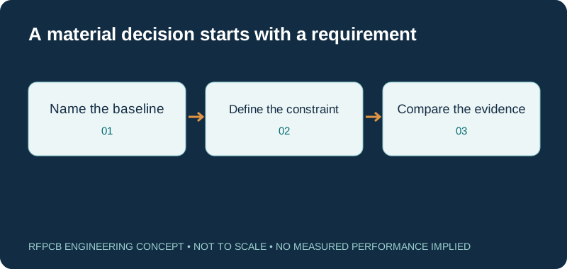
An engineer trying to reduce a long transmission line’s loss needs a different comparison from a buyer trying to reduce the cost of a low-volume prototype. Write the problem in one sentence and identify the quantity that would demonstrate improvement. Examples include an allowed insertion loss over a stated band, an agreed board envelope or a comparable delivered-price quotation.
Keep constraints next to that objective. Existing component placement, an approved connector, a fixed dielectric spacing or a customer material restriction can narrow the options before Dk is discussed. A useful comparison produces a reviewable shortlist and identifies the evidence still missing. It does not announce a universal winner across every RF application.
Compare grades and constructions, not brand names
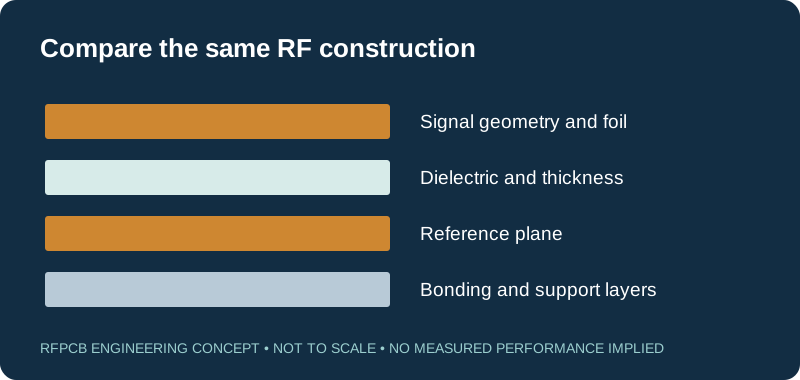
Rogers, Taconic, Panasonic and Shengyi each cover more than one material construction. Their product names should not be treated as interchangeable electrical specifications. Include the complete grade, nominal dielectric thickness, foil type and any bonding material in the comparison. For a hybrid board, identify which layers carry the RF circuit and which supply mechanical or digital support.
The same care applies to related suffixes. A thermally enhanced variant or a different glass style can carry different properties and processing requirements. The material selection guide helps organize these variables. Keep the selected manufacturer documents with the engineering package so the reason for the choice remains visible at repeat order.
Keep process Dk, design Dk and effective permittivity separate
Process Dk is associated with a defined material test. A manufacturer’s design Dk is intended for a stated circuit-modeling context. Effective permittivity also depends on the electromagnetic structure, such as a surface microstrip and its surrounding fields. These values can be related without being numerically identical or substitutable in every calculation.
The comparison pages identify the role of a value instead of presenting one number as the entire material definition. Use the impedance calculator as an initial geometry aid, then confirm the production construction and model. When an existing circuit must keep its frequency response, evaluate geometry, thickness and fringing alongside material properties rather than changing only one spreadsheet cell.
Loss comparisons require consistent boundaries
A published dissipation factor at one frequency should not be used to rank a finished board against a value measured at another frequency without an appropriate model. Copper roughness, conductor width, surface finish, launches, vias and connectors can all matter to the measured path. State whether the requirement applies to a uniform line, a connectorized coupon or the complete circuit.
Use the loss-reduction guide to separate the budget terms. When prototype measurements are compared, record the reference planes and any de-embedding. Preserve the unprocessed measurement context along with the result used for acceptance. Otherwise, an apparent material improvement may be a change in the fixture or measurement boundary.
Manufacturing feasibility belongs in the comparison
A material choice affects more than the circuit simulation. Hole preparation, dimensional control, bonding layers and lamination sequence need review on the complete build. A simple double-sided coupon does not automatically qualify a multilayer assembly with cavities, sequential lamination or mixed dielectric through holes. Ask which features control feasibility for the actual drawing.
Identify permitted changes before requesting an alternative quotation. A different nominal core thickness may need artwork changes, and a bonding substitution can change the finished dielectric spacing. The hybrid stackup guide is a useful companion when a proposal combines RF and FR4 layers. Keep circuit approval and process approval explicit.
Compare delivered cost and qualification effort
Material sheet price alone does not determine the cost of accepted boards. Panel utilization, quantity, setup, inspection, extra coupons, assembly and shipment all contribute to a quotation. Enter comparable scopes into the RF PCB cost worksheet. Label each rate as a reviewed quotation or an illustrative assumption.
A material change also has a one-time cost: engineering review, layout adjustment, prototypes and measurements. The lower-cost-alternatives guide includes a break-even calculation using entered figures. It does not supply a supplier price list. A lower recurring price can still be the wrong decision when the order is small or the alternative has not met the acceptance requirement.
Make the prototype answer the unresolved question
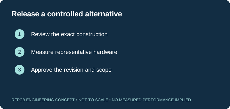
Choose representative structures rather than ordering an arbitrary sample and hoping it proves everything. A filter comparison may require controlled coupling gaps and resonator lengths. A power amplifier may need the actual thermal path and assembly interfaces. A phase-sensitive feed can require matched routes and a defined channel-to-channel measurement.
Record the material identity, board revision and measured dimensions for each sample. Where possible, change one factor at a time. If several factors must change together, describe the work as a construction comparison. The test report guide explains how to connect the sample, method, limits and reported result without claiming more than the measurement establishes.
Turn a comparison into an approved manufacturing record
A comparison is complete when the engineering owner can state which construction is approved, what evidence supports it and which later changes require review. Keep the accepted drawing, material specification, test plan and any concessions aligned. A purchasing note saying “equivalent material” is insufficient if the original circuit depends on a particular foil or dielectric spacing.
Use the preparation checklist below to identify what is documented and what remains an open question. It is a self-assessment, not a substitute for file inspection. For an RFQ, include quantities and the target delivery basis alongside the technical package. This lets engineering and purchasing evaluate the same proposed build.
Prepare a reviewable engineering request
Check only the requirements you have actually documented. This list records readiness; it does not inspect your files or certify a design. Missing information is useful: identify it explicitly so the engineering review can resolve it before a production release.
These inputs are processed in your browser and are not submitted by this tool. The downloaded summary is a plain-text planning record. Use the secure quote form to send files; request an NDA first if your project requires one.
Manufacturing context
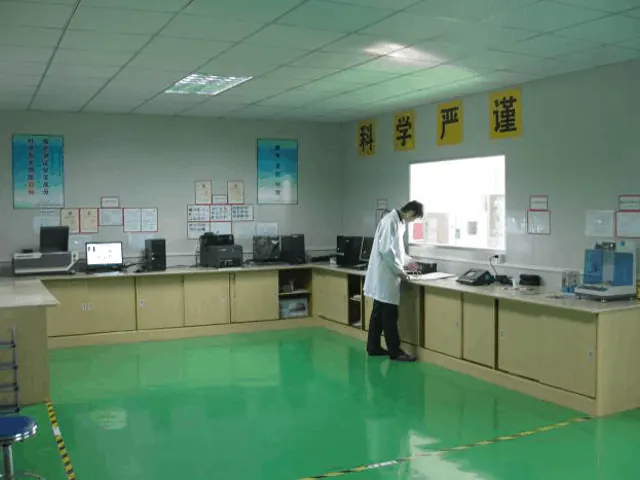
RFPCB and PCBSync share the manufacturing facility shown below. These process photographs illustrate the production environment; they are not evidence that a particular board, material grade or RF performance has been qualified. Request the documentation and inspection scope applicable to your project.


Questions before you continue
Which RF PCB material is best?
The answer depends on the circuit, construction, manufacturing constraints and acceptance plan. Start with a named baseline and a measurable requirement; use the relevant comparison to prepare the shortlist.
Can matching Dk prove that two materials are equivalent?
No. Test method, thickness, foil, loss behavior, bonding and the complete circuit need review. Similar nominal Dk is a screening observation, not a substitution approval.
Should I use a comparison page as a fabrication specification?
No. Use the applicable manufacturer document and the approved drawing and stackup. These guides explain decisions and identify information needed for a project-specific review.
Can I quote two candidate materials?
Yes: name both constructions, identify fixed constraints and request comparable quantities and tests. Availability, process feasibility and final price require a reviewed quotation.
Continue your engineering review
Bring the decision into your manufacturing review
Send the exact material, construction and question you need to resolve. Include the drawing revision and requested evidence so the review can connect the technical decision to a defined quotation.
Sources and engineering scope
Manufacturer values apply to the identified grade, test method and construction. Engineering examples on this page are illustrative; they are not measured product results, inventory statements or certification claims. Manufacturer and product names belong to their respective owners. Keep the applicable datasheet revision with your approved manufacturing package.
In this section
2 vs 4 Layer RF PCB: Performance, Cost & Choice
View page24 GHz vs 77 GHz Radar | Resolution, Cost & Rules
View page77GHz vs 79GHz Radar: Band, Resolution & PCB Guide
View pageAltium vs KiCad RF: Which EDA Fits Your Board?
View pageAOI vs X-Ray PCB Inspection for RF Boards
View pageChip vs PCB Antenna: How to Choose the Right One
View pageENIG vs ENEPIG RF: Which Finish Wins?
View pageENIG vs Immersion Silver for RF | Loss & Cost
View pageFMCW vs Pulse Radar | Architecture & PCB Impact
View pageFR4 vs High Frequency Laminate: Full Comparison
View pageGCPW vs Microstrip | mmWave Transmission Line Choice
View pageHFSS vs CST vs ADS: RF Simulation Tool Comparison
View pageHybrid vs Full Rogers Stackup | Cost Saving Analysis
View pageI-Tera vs RO4350B: Which Laminate Fits?
View pageIPC Class 2 vs 3: RF PCB Acceptance Criteria
View pageLaser vs Mechanical Drill for RF PCB Vias
View pageLower-Cost Rogers PCB Alternatives
View pageMegtron 6 vs 7: Properties, Loss, Cost & When to Use Each
View pageMegtron 7 vs Tachyon 100G | Ultra Low Loss Compared
View pageMicrostrip vs CPW | Which Topology for mmWave PCB
View pageMicrostrip vs Stripline | Loss, Radiation & Density
View pagePatch vs Dipole Antenna | PCB Antenna Selection
View pagePIFA vs Monopole Antenna for Compact Devices
View pagePlasma vs Sodium Etch for PTFE | Reliability Compared
View pagePTFE vs Ceramic PCB | Thermal and RF Trade-offs
View pagePTFE vs Hydrocarbon PCB Laminates
View pagePTFE vs LCP | Which for mmWave and Flexible RF
View pageRadar vs LiDAR | Sensor Selection & PCB Differences
View pageRO3003 vs Astra MT77 | 77 GHz Radar Laminates
View pageRO3003 vs FastRise 27 | mmWave Laminate Comparison
View pageRO3003 vs RO3003G2 | What Changed in Gen 2
View pageRO3003 vs RO4350B
View pageRO4003C vs RO4835 | Oxidation Resistance Compared
View pageRO4350B vs AD350A | Full Parameter Comparison
View pageRO4350B vs Kappa 438 | Rogers In-House Comparison
View pageRO4350B vs RF-35: Full Parameter & Cost Comparison
View pageRO4350B vs RO4003C
View pageRO4350B vs S7136 | Which Laminate for Your RF PCB
View pageRO4350B vs Wangling TP-2 | Low-Cost Equivalent Test
View pageRO4360G2 vs RO3010 | High-Dk Laminate Comparison
View pageRogers RO4350B vs Taconic RF-35
View pageRogers vs Arlon | RF PCB Laminate Brand Comparison
View pageRogers vs FR4 for RF | Loss Data at 1–20 GHz
View pageRogers vs Isola | Which Brand for Your RF Design
View pageRogers vs Panasonic Megtron | RF vs High-Speed Digital
View pageRogers vs Shengyi | High-Frequency Laminate Compared
View pageRogers vs Ventec | Low-Loss Laminate Alternatives
View pageRogers vs Wangling F4B | China Alternative Verified
View pageRT5880 vs F4B: PTFE Laminate Comparison Guide
View pageRT5880 vs RT5870: Dk, Loss and Design Guide
View pageRT5880 vs TLY-5: PTFE Laminate Comparison
View pageRT6002 vs RT6010: High-Dk or Low-Loss PTFE?
View pageSub6 vs mmWave: 5G PCB Design Differences
View pageTaconic vs Arlon | PTFE Laminate Brand Comparison
View pageTC350 vs 92ML | Thermal RF Laminate Compared
View pageTC350 vs RT/duroid 6035HTC | Thermal Conductivity
View pageTDR vs VNA | Which Impedance Measurement to Trust
View pageVLP vs HVLP Copper | ED RTF Loss & Adhesion Guide
View pageReady for a quotation?
Send your requirements for a material, stackup and manufacturing review. Price and schedule are confirmed for your project.