
Preserve the antenna geometry. Define the radar evidence.
A 77 GHz automotive radar PCB needs a controlled RF construction, repeatable antenna geometry and a project-specific qualification plan. The PCB is one part of the sensor; vehicle-level performance cannot be established by a laminate choice alone.
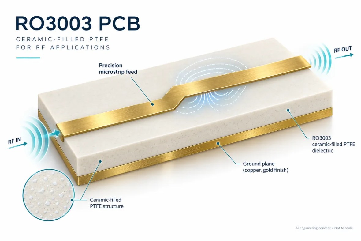
A 77 GHz automotive radar PCB needs a controlled RF construction, repeatable antenna geometry and a project-specific qualification plan. The PCB is one part of the sensor; vehicle-level performance cannot be established by a laminate choice alone. Use the application-specific review below to identify the information needed for material selection, fabrication and acceptance.
Start with the radar architecture and occupied bandwidth
A radar sensor combines a transceiver, antennas, clock and power circuitry, processing and a mechanical installation. A 77 GHz label describes an operating region, not all the waveform or manufacturing requirements. State the actual frequency range, antenna configuration, occupied bandwidth and device reference design used by the project.
For FMCW radar, the ideal range-resolution relationship depends on usable sweep bandwidth. It is distinct from maximum detection range, accuracy, angular resolution and velocity resolution. The calculator below deliberately shows only the ideal bandwidth relationship. It cannot predict vehicle detection performance or replace the sensor developer’s signal-processing model.
Protect the antenna and transition geometry
At millimeter-wave frequencies, antenna dimensions and transition details deserve careful control. Define the layer stackup, copper profile, critical artwork dimensions, mask openings and surface-finish areas. Registration between an RF layer, its reference and the relevant mechanical features may also be important.
Use the device manufacturer’s current layout guidance and reference data as a starting point, then review changes introduced by the final product. An enclosure, radome, mounting angle or nearby metal can alter the electromagnetic environment. Manufacturing to an antenna artwork does not independently prove the assembled sensor’s field of view or target-detection behavior.
Understand the application interfaces
Ideal FMCW range-resolution estimate
Explore usable sweep bandwidth and ideal range resolution. This is not maximum range, accuracy or a sensor detection prediction.
ΔR = c / (2B), c = 299,792,458 m/s. Ideal waveform relationship; processing windows, usable sampled bandwidth and practical detection behavior can change the observed result.
Material selection is construction-specific
A material such as RO3003 can be considered when its properties and available construction fit the design. The exact grade, thickness, foil and design model must be specified. Avoid treating every variant of a material family as identical or assuming that a nominal Dk value fully defines its behavior at the operating frequency.
A hybrid stackup may integrate an RF region with digital and power layers, but bonding materials, symmetry and local field regions still require review. A process change that affects antenna geometry, dielectric thickness or copper surface should follow the agreed change-control procedure rather than being treated as an invisible substitution.
Separate board evidence from automotive qualification
Define which bare-board records, assembled measurements and environmental tests belong to the project. Impedance or continuity evidence alone does not establish a radar function. A representative RF test and the sensor-level validation plan should identify the fixtures, calibration, waveform, operating conditions and pass criteria.
Automotive program requirements may include customer-specific approval, traceability and documentation. Request the actual certificate, legal entity, site and applicable scope when supplier certification is required. This application page is not a claim that every board is automotive-qualified, that a sensor meets functional-safety requirements, or that a particular production approval has been granted.
Application-to-manufacturing review
| Area | Define for the application | Confirm before release |
|---|---|---|
| Radar scope | Frequency range, waveform and antenna architecture | Bandwidth and device-specific implementation |
| RF construction | Material, foil, thickness and antenna artwork | Critical dimensions, registration and surface condition |
| Product environment | Radome, mounting and nearby structures | Representative assembled test configuration |
| Qualification | Customer requirements and traceability plan | Actual documentation and sensor-level acceptance |
Connect these requirements to the High Frequency PCB Manufacturing workflow. The approved stackup, drawing and order-specific acceptance plan define the build.
Build the acceptance plan around the application
Decide what the bare board must demonstrate and what belongs to the assembled product. Continuity testing, an impedance coupon, a calibrated RF network measurement and an installed-system test are different forms of evidence. None should silently stand in for another. Identify the required report, coverage, limits and review responsibility before the quotation is accepted.
Record the test configuration alongside the result: board revision, material construction, fixture, calibration, firmware or device settings, temperature and the relevant operating point. When comparing prototypes, keep these conditions consistent or explain the difference. A changed connector, cable or reference plane can make an apparent board improvement difficult to interpret.
For production, agree how first-article findings become controlled manufacturing requirements. Identify which dimensions and material choices are critical, what may be adjusted by engineering, and which changes require renewed validation. A repeat order should reference the approved revision and test plan rather than rely on a previous email description.
Visit quality and test evidence for supplier qualification and reporting questions. Where a customer program requires certificates or sector-specific approval, request the actual documents and applicable scope. An application example is not a product certification or a substitute for the customer’s acceptance process.
Prepare a quotation that engineering can review
A useful RF PCB quotation starts with a controlled design package. Send Gerber or an agreed manufacturing format, NC drill data, a dimensioned outline, the board revision and a stackup drawing. Add quantity, delivery destination and the requested schedule. If some details are still open, mark them explicitly instead of letting a drawing, an email and a file name imply different requirements.
Separate mandatory requirements from preferences. A specified laminate, a customer-approved alternative and a request for a recommendation are three different purchasing instructions. State whether the supplier may propose changes to dielectric thickness, line geometry, panelization or finish, and who approves those changes. Changes that affect RF behavior should return to the design owner before release.
What affects the price?
Board area and panel utilization, quantity, material availability, stackup complexity, drilling and plating, special mechanical features, inspection and test all influence cost. Tight tolerances can also change the achievable yield and process route. An online estimate cannot account for every interaction in an unusual construction.
Use the panel and material cost tool to explore the assumptions it exposes, then request a reviewed quotation. Confirm tooling or setup charges, engineering changes, shipping, taxes and the included report package in the commercial offer.
What affects delivery?
Material stock, engineering clarification, special tooling, lamination cycles and the agreed inspection plan can affect the schedule. Assembly adds component procurement, stencil preparation, programming and fixture readiness. The requested date is a planning input until the supplier confirms the complete order scope.
The website’s response-time target describes enquiry handling. It is not a guarantee that a complex RF build can be priced, fabricated or delivered within the same period. Ask the team to identify the critical dependencies for your project.
From review to repeatable production
Agree the build
Engineering reviews material, geometry, mechanical features and test requirements. Open questions and proposed changes are documented. The approved drawing and stackup become the manufacturing baseline.
Verify the first build
Define which records are needed for the prototype: electrical test, impedance, dimensional inspection, cross-sections or an agreed RF measurement. Evaluate the evidence against the relevant acceptance criteria.
Control later changes
Keep revision, material substitutions, process changes and test updates traceable. A successful prototype is the starting point for production control, not permission to change the construction silently.
For a performance issue, retain the board revision, lot reference, measurement setup and operating conditions. Comparing repeatable measurements is more useful than comparing screenshots taken with different fixtures or calibration. Define the investigation and disposition with the supplier using the actual order requirements.
Prepare your 77 GHz automotive radar PCB enquiry
Select what is ready. This checklist runs locally and does not upload files or place an order.
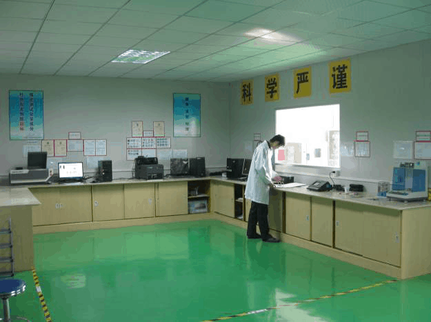
Real manufacturing and laboratory context
These photographs are from the shared RFPCB / PCBSync facility archive. They show manufacturing and laboratory areas, not a claim that a pictured item is a certified 77 GHz automotive radar PCB product. Review the actual process and report requirements with the team.


77 GHz Automotive Radar PCB Manufacturing: common questions
Does the bandwidth calculator predict detection range?
No. It estimates ideal range resolution only. Detection range and accuracy depend on many additional system factors.
Is a board using RO3003 automatically qualified for automotive radar?
No. Qualification applies to the specific design, manufacturing process and customer program.
Can the reference antenna artwork be used unchanged?
Only after reviewing the final stackup and product environment. Changes can require renewed RF validation.
Related application decisions
Antenna PCB Design & Manufacturing
An antenna PCB must preserve the radiator geometry, feed network and surrounding electromagnetic environment. Review the laminate, reference planes, enclosure and measurement method together before manufacturing.
5G & mmWave PCB Manufacturing
A 5G or millimeter-wave PCB brings RF interconnects, antenna structures and digital control into a tightly coupled design. Select the stackup around the actual operating band and bandwidth rather than the 5G label alone.
Phased Array PCB Design & Manufacturing
A phased array PCB integrates repeated RF channels, radiating elements and control. Element pitch, channel matching, thermal behavior and calibration must be considered together for communication and sensing arrays.
Technical references and scope
Use current component and material documentation together with the approved design. The sources below provide engineering context; the specific product and manufacturing acceptance requirements remain project-dependent.
- TI automotive 77 GHz reference design
- TI FMCW radar parameter guidance
- RFPCB material selection and engineering tools
- Manufacturing capability review
Engineering guide updated September 2026. Diagrams are conceptual and not production drawings. Calculations are estimates under the stated assumptions.
Bring the application requirements into the quote.
Send the operating band, board revision, stackup, quantity and acceptance needs. The team can identify missing information and review the proposed manufacturing scope.
Ready for a quotation?
Send your requirements for a material, stackup and manufacturing review. Price and schedule are confirmed for your project.