
Build around the RF requirement.
High frequency PCB manufacturing combines a suitable laminate with controlled geometry, return paths and an agreed test plan. Start with the operating band, loss budget and assembly environment, then choose a construction the factory can repeat.
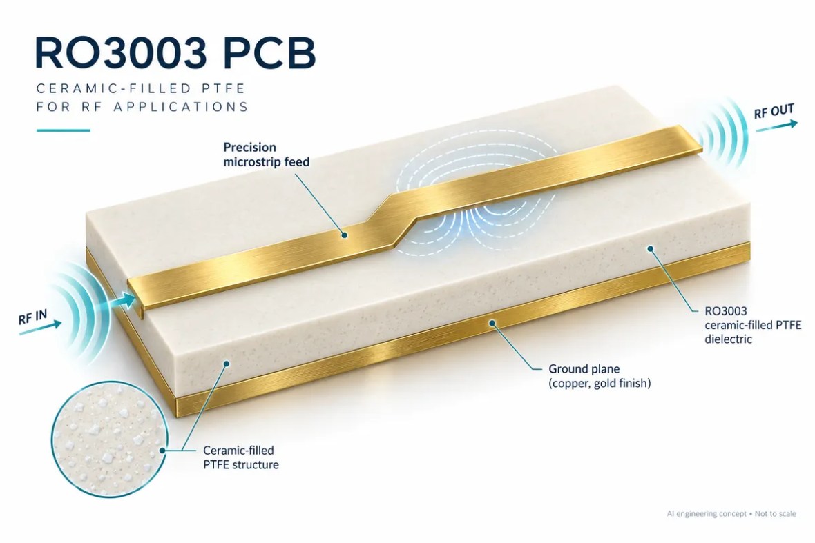
High frequency PCB manufacturing combines a suitable laminate with controlled geometry, return paths and an agreed test plan. Start with the operating band, loss budget and assembly environment, then choose a construction the factory can repeat. Review the build-specific requirements below and use the interactive tool to prepare better engineering questions.
What makes a PCB a high frequency board?
A high frequency PCB is designed so that interconnect geometry and material properties support the intended radio-frequency or microwave behavior. The distinction is not a single universal frequency threshold. A short control trace and a long antenna feed can have very different requirements at the same operating frequency. Electrical length, acceptable attenuation, phase accuracy and the device interface determine when an ordinary routing assumption becomes inadequate.
Material selection should begin with the whole circuit. A receiver front end may emphasize low loss and stable matching; an antenna array may emphasize phase tracking across many paths; a power amplifier may emphasize heat flow alongside electrical performance. A laminate name alone does not define these outcomes. Copper profile, final finish, solder mask, connector transitions and the manufactured dimensions all contribute to the finished structure.
Choose the laminate for the application
Use RO4350B or RO4003C as candidates when a hydrocarbon ceramic construction fits the electrical and processing requirements. Consider RO3003 and RT/duroid 5880 when their specific dielectric properties justify a different processing route. These are starting points for comparison, not interchangeable grades.
Specify the manufacturer’s exact material designation, dielectric thickness and copper option. Keep process Dk, design Dk and effective permittivity separate: they are used for different purposes and can be obtained by different methods. A simulation should document the value used, its frequency and its source. The material selection guide helps organize candidates before a stackup is frozen.
Three views of the engineering decision
Electrical length explorer
Estimate guided wavelength and phase using a user-specified effective permittivity. This is not a material-Dk lookup or a field solver.
λg = 299.792458 / (fGHz × √εeff) mm; phase = 360 × length / λg. Constant effective permittivity; dispersion, loss and transitions are omitted.
Control the geometry that the field sees
For a microstrip, the distance to the reference plane matters as much as the drawn trace width. For a grounded coplanar line, the lateral gap and ground-via environment also matter. A stripline depends on both surrounding dielectric regions and reference planes. Confirm the actual construction before treating a calculator output as a routing rule.
Keep sensitive RF paths clear of unintended plane discontinuities. Where a layer transition is necessary, review the return-current path, via barrel, unused stub and connector launch together. Avoid sending only a nominal impedance target: identify the layer, net class, reference plane, geometry and mask condition. Use the controlled impedance service to define the manufacturing and verification requirements.
Manufacturing review and acceptance
The engineering review checks the stackup, drill architecture, copper distribution, artwork compensation, finish and inspection needs. A mixed RF and control design may benefit from a hybrid stackup, but the RF field still needs a suitable local dielectric and reference structure. Cost savings must be evaluated against lamination complexity, yield and the required test evidence.
Bare-board continuity testing answers whether the manufactured nets are connected correctly. It does not establish insertion loss, antenna gain or amplifier efficiency. Define any impedance coupons, RF coupons, S-parameter measurements or system tests before ordering, including reference planes and the measurement conditions. This prevents a disagreement about what a passing board is supposed to demonstrate.
What the manufacturing review needs
| Review area | Define in your package | Confirm before release |
|---|---|---|
| Material | Exact grade, foil type and dielectric thickness | Dk/Df method, frequency and permitted alternatives |
| RF interconnect | Microstrip, stripline or coplanar geometry | Trace dimensions, reference planes and mask |
| Transitions | Connector and via details | Launch model, residual stub and return path |
| Acceptance | Electrical plus agreed RF evidence | Coupon, method, limits and reporting |
These are review requirements, not universal capability limits. The order-specific drawing, process window and acceptance plan control the build.
Prepare a quotation that engineering can review
A useful RF PCB quotation starts with a controlled design package. Send Gerber or an agreed manufacturing format, NC drill data, a dimensioned outline, the board revision and a stackup drawing. Add quantity, delivery destination and the requested schedule. If some details are still open, mark them explicitly instead of letting a drawing, an email and a file name imply different requirements.
Separate mandatory requirements from preferences. A specified laminate, a customer-approved alternative and a request for a recommendation are three different purchasing instructions. State whether the supplier may propose changes to dielectric thickness, line geometry, panelization or finish, and who approves those changes. Changes that affect RF behavior should return to the design owner before release.
What affects the price?
Board area and panel utilization, quantity, material availability, stackup complexity, drilling and plating, special mechanical features, inspection and test all influence cost. Tight tolerances can also change the achievable yield and process route. An online estimate cannot account for every interaction in an unusual construction.
Use the panel and material cost tool to explore the assumptions it exposes, then request a reviewed quotation. Confirm tooling or setup charges, engineering changes, shipping, taxes and the included report package in the commercial offer.
What affects delivery?
Material stock, engineering clarification, special tooling, lamination cycles and the agreed inspection plan can affect the schedule. Assembly adds component procurement, stencil preparation, programming and fixture readiness. The requested date is a planning input until the supplier confirms the complete order scope.
The website’s response-time target describes enquiry handling. It is not a guarantee that a complex RF build can be priced, fabricated or delivered within the same period. Ask the team to identify the critical dependencies for your project.
From review to repeatable production
Agree the build
Engineering reviews material, geometry, mechanical features and test requirements. Open questions and proposed changes are documented. The approved drawing and stackup become the manufacturing baseline.
Verify the first build
Define which records are needed for the prototype: electrical test, impedance, dimensional inspection, cross-sections or an agreed RF measurement. Evaluate the evidence against the relevant acceptance criteria.
Control later changes
Keep revision, material substitutions, process changes and test updates traceable. A successful prototype is the starting point for production control, not permission to change the construction silently.
For a performance issue, retain the board revision, lot reference, measurement setup and operating conditions. Comparing repeatable measurements is more useful than comparing screenshots taken with different fixtures or calibration. Define the investigation and disposition with the supplier using the actual order requirements.
Is your high frequency PCB package ready?
Select what is ready. This checklist runs locally and does not upload files or place an order.
The factory behind the engineering review
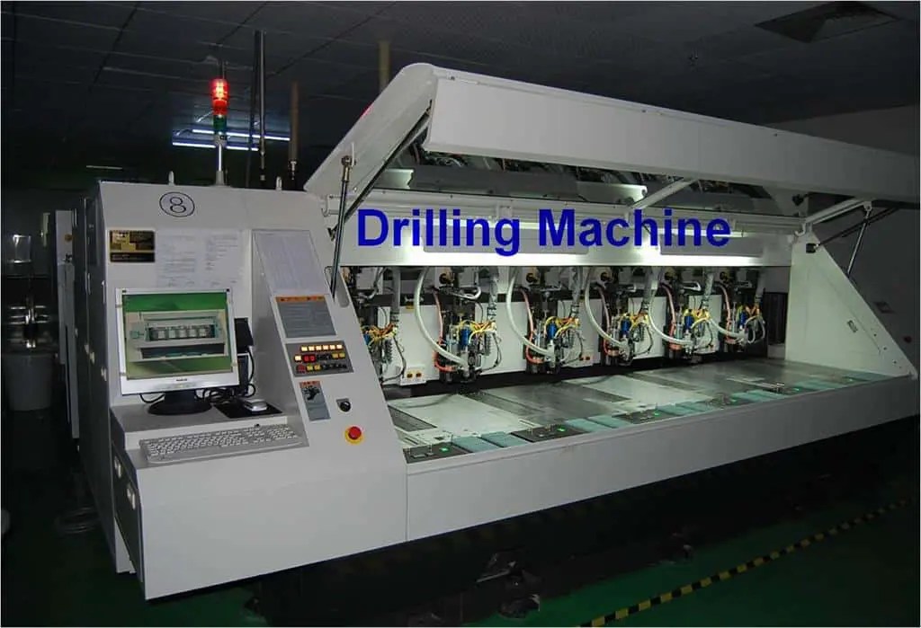
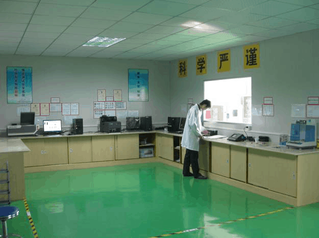
Use real process and laboratory evidence when qualifying a supplier. The photographs below come from the shared RFPCB / PCBSync facility archive. Discuss the equipment and inspection records relevant to your order through our quality page.

High Frequency PCB Manufacturing: common questions
Is there one frequency above which FR-4 cannot be used?
No. Evaluate route length, loss, phase, variability and the exact FR-4 construction. A frequency label alone is not a sufficient material specification.
Can you recommend a cheaper RF laminate?
Request an alternative review with the original stackup and electrical limits. Any substitution needs customer approval and may require simulation and validation.
Does a 50-ohm coupon prove my antenna performance?
No. A coupon verifies the agreed transmission-line impedance measurement. Antenna performance requires the appropriate RF or system test.
Continue the engineering review
Controlled Impedance PCB Manufacturing
Controlled impedance PCB manufacturing turns a nominal electrical target into a reviewed geometry, material construction and measurement plan. Specify the controlled nets and acceptance window before fabrication begins.
Hybrid Stackup PCB — Rogers + FR-4
A hybrid stackup combines different laminate systems within one PCB. Use a suitable RF dielectric around critical structures and a compatible construction for power, control and digital routing, with the full lamination system reviewed before release.
Surface Finishes for RF PCB
An RF PCB surface finish must support soldering, handling and the intended electrical performance. Compare ENIG, immersion silver, OSP and other finishes using the actual circuit geometry and assembly requirements.
Technical references and manufacturing scope
The engineering explanations distinguish ideal estimates from production acceptance. Use current material data and the approved drawing for the actual build. RFPCB and PCBSync share a manufacturing operation; the shared factory overview and rigid-board capability table provide context, while specific combinations require review.
- Rogers engineering tools and material calculations
- Rogers: RO4000 / FR-4 hybrid flatness
- Rogers: circuit materials and high-frequency losses
- Texas Instruments: AFE79xx layout and via-transition guidance
Engineering guide updated September 2026. Schematics illustrate concepts and are not fabrication-ready drawings. Product and material names belong to their respective owners.
Send the construction, not just the keyword.
Share your board revision, stackup, quantity and the requirements that matter. The team can identify open questions and confirm the manufacturing and test scope before quoting.
Ready for a quotation?
Send your requirements for a material, stackup and manufacturing review. Price and schedule are confirmed for your project.