
Understand the decision behind an RF PCB build.
Explore six representative engineering scenarios. Follow the challenge, review route and evidence needed for release, then bring a comparable question to our team.
Find an example close to your design
Filter by application or search a technical term such as loss, thermal or stackup. Each example describes the evidence to request rather than promising a particular outcome.
No matching examples. Clear the search or choose another application.
Antenna feed network: geometry before material substitution
Challenge. A printed antenna feed must fit a fixed mechanical envelope while preserving its impedance and loss budget. An attractive laminate alternative is proposed during quotation, but the original model used a different design Dk and dielectric thickness.
Engineering review. Compare the exact grades, thicknesses and copper options. Recalculate the relevant transmission-line geometry, review the connector launch and identify the antenna tuning that depends on the substrate. Keep the housing, mounting and ground environment in the evaluation rather than testing only an isolated trace.
Evidence to request. Request the approved stackup, controlled-net definition and coupon scope. For the antenna, agree the assembled configuration, matching measurements and radiation evidence required by the design owner. Record the conditions used for each comparison.
Release decision. Approve a substitution only after the appropriate model and prototype review. A similar datasheet number alone does not establish that the antenna is unchanged.
Antenna PCB engineering5G and mmWave: define the loss measurement boundary
Challenge. A short interconnect is expected to meet a tight insertion-loss budget. The initial comparison mixes a dielectric-only estimate with a connectorized board measurement, making the apparent discrepancy difficult to diagnose.
Engineering review. Define ports and calibration reference planes, separate line length from launches and fixtures, and confirm the modeled Dk, Df, copper profile and surface finish. Decide whether the comparison should use de-embedded line data or the complete connectorized path. Keep both quantities clearly labeled.
Evidence to request. Request the actual construction, relevant geometry measurements and a test plan identifying frequency range, fixtures and treatment of transitions. Preserve both the raw measurement context and the processed result used for acceptance.
Release decision. Use consistent boundaries before changing the laminate or narrowing a process tolerance. An improved partial model does not by itself demonstrate that the complete RF path meets its budget.
5G and mmWave review77 GHz radar: preserve the launch and mechanical interface
Challenge. An automotive radar prototype includes a sensitive transition and a tightly constrained sensor enclosure. A mechanical drawing revision changes a mounting detail near the RF path while the board artwork remains on an earlier revision.
Engineering review. Reconcile the mechanical and electrical package before release. Review connector or antenna transitions, reference planes, finish and registration requirements as one assembly. Identify which dimensions need manufacturing inspection and which performance questions require assembled testing.
Evidence to request. Agree the revision baseline, critical dimensions, material identity and prototype test conditions. Any automotive qualification requirements need their own documented scope and acceptance route; an RF board inspection report is not a substitute for product qualification.
Release decision. Release one coherent package and carry the accepted prototype configuration into later builds. Do not infer radar range, accuracy or system compliance from a generic board capability statement.
77 GHz radar PCB guidePhased array: compare channels under the same conditions
Challenge. A multi-channel feed network needs repeatable amplitude and phase behavior. Individual traces meet their nominal impedance targets, yet the design review has not defined how channel-to-channel consistency will be measured.
Engineering review. Identify the complete signal paths, reference planes and transitions. Review length matching, stackup symmetry, material construction and the interfaces to active devices. Define whether acceptance applies to bare-board structures, assembled channels or a calibrated system.
Evidence to request. Request a channel map, the relevant dimensional and impedance records, and a repeatable measurement procedure with common frequency and calibration conditions. Preserve the assembly state and environmental conditions with any channel-comparison report.
Release decision. Agree the variation limits and the responsibility for calibration before production. A nominal impedance result is useful evidence for one structure, but it does not establish the complete array phase distribution.
Phased-array PCB requirementsRF power amplifier: include the thermal interface
Challenge. A power amplifier board combines an RF matching network with a demanding heat path. A heavier-copper proposal addresses current handling, but the package-to-heatsink interface and assembly constraints remain undefined.
Engineering review. Review RF power and bias conditions, device mounting, thermal vias or other heat-transfer features, board flatness and the external cooling interface. Check whether copper or finish changes affect the modeled matching geometry and the assembly process.
Evidence to request. Request a documented construction, mechanical interface drawing and test conditions identifying the operating point and cooling arrangement. Define inspection of the features that control the heat path, together with the required assembled RF and thermal measurements.
Release decision. Evaluate the board and cooling assembly together. A material thermal-conductivity number or copper-weight increase alone cannot demonstrate a safe device temperature or the intended amplifier performance.
RF power-amplifier PCB guideHybrid RF and digital: control the construction change
Challenge. A mixed RF and digital board uses a specialist laminate near the RF path and a different material for other layers. A cost review proposes a new bonding arrangement without a corresponding update to the controlled-impedance model.
Engineering review. Name every core and bonding layer, define finished dielectric spacing and review the intended lamination sequence. Revisit impedance, registration, thermal behavior and the mechanical envelope when the construction changes. Compare quotations on the same complete scope.
Evidence to request. Request the revised stackup, material identifiers, engineering approval record and inspection requirements. A prototype review should capture the actual build and the measurement conditions used to accept it, so the construction can be repeated.
Release decision. Approve the revised construction as a controlled engineering change. An example stackup or a material cross-reference shortlist is a discussion aid, not an automatic manufacturing release.
Hybrid stackup manufacturingHow to read an RF PCB case study
A useful case study identifies the problem, the construction and the method used to decide whether a change worked. Read the starting condition before the result. The operating frequency, line geometry, copper option, finish, assembly state and measurement boundary can all affect whether an example is relevant to your design. A result without those conditions is difficult to transfer into an engineering decision.
Separate design intent from manufacturing evidence. A fabrication inspection can establish particular dimensions or electrical properties under an agreed method. A system claim such as antenna gain, radar accuracy or amplifier efficiency needs a corresponding system-level test. The strongest project review connects these layers of evidence while keeping their limitations visible.
These examples are structured around that distinction. They help you prepare the questions and acceptance conditions for your own project. They are not a portfolio of customer-approved production results, and they should not be used to infer a promised improvement in your design.
What a documented project reference should contain
A defined baseline
The board revision, laminate and stackup, critical geometry, circuit function and initial constraint. If a change is being compared, both configurations should be identified.
A reviewable intervention
The design or manufacturing change, why it was selected, who approved it and which other variables were kept consistent. Include relevant DFM and assembly decisions.
A bounded result
The test method, frequency or operating point, sample context, acceptance limits and permitted conclusion. Include publication permission before sharing customer information.
The manufacturing context behind the discussion
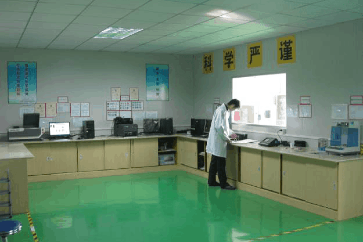
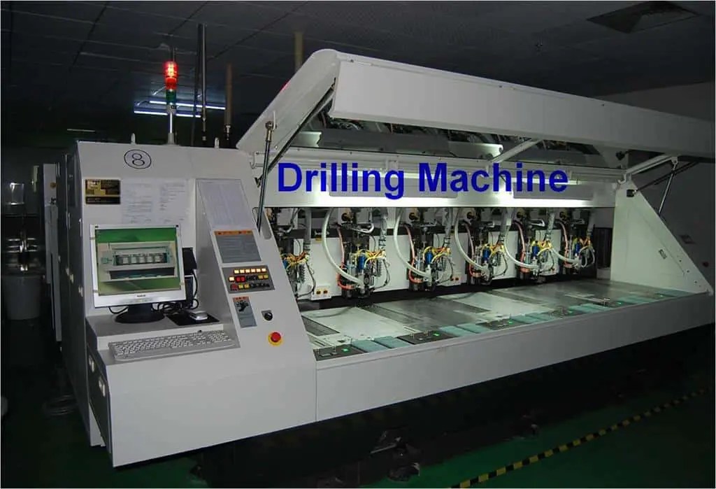
The shared factory archive below shows process and laboratory areas. The images support a conversation about manufacturing resources; they do not serve as evidence that the illustrative designs above were built or tested. For current equipment and supplier-review questions, visit the factory page.


Request a relevant reference without disclosing the design
Begin with a non-confidential description of the application, material family, frequency band and main engineering difficulty. Explain whether you need a fabrication reference, an assembly example or a test-method discussion. The team can then establish what information is relevant and available for sharing.
If your supplier-qualification process requires actual project records, say which evidence is needed and why. An anonymized description may be sufficient for an initial discussion, while a deeper technical review may require permission and a confidentiality agreement. Customer drawings, test results and photographs should be treated according to the relevant agreement rather than assumed to be public.
Use the NDA page before sharing restricted files. Once the disclosure route is agreed, provide a coherent package and list the questions that must be answered before quotation or release. A precise request is more useful than asking whether the factory has made something generally similar.
Prepare your comparable-project request
Select what is ready. This checklist runs locally and does not upload files or place an order.
Continue your supplier review
Understand the process
Review the factory, manufacturing capabilities and quality and test scope together. Match the production route and requested records to the board you intend to build.
Prepare the engineering package
Use the RF PCB design guide, stackup concepts and engineering examples to organize the decisions that remain open before quotation.
Plan the handoff
Review the NDA request process before confidential disclosure. Use the lead-time planner to discuss the required ship date and arrival date separately with the team.
Frequently asked questions
Are these verified customer success stories?
The six cards are illustrative engineering scenarios, not verified customer projects. They do not claim measured customer outcomes or identify confidential designs.
Can I request a comparable project reference?
Yes. Describe the material, application and technical challenge. Ask the team whether a relevant reference can be shared with the required permission and supporting evidence.
Why are there no percentage improvement claims?
A meaningful improvement claim needs an identified baseline, construction, method and test conditions. Those project records are not presented for these examples.
Can the same solution be reused on my board?
Use the review questions as a starting point. Your geometry, operating conditions, assembly and acceptance requirements must be evaluated separately.
Technical routes for your own review
Use the microstrip estimate, loss-budget tool and sourced material table with their stated assumptions. Confirm the production construction and acceptance evidence through the quality review.
Bring a comparable engineering challenge.
Tell us what needs to be decided, what has already been measured and what evidence your team needs before the next build.
Ready for a quotation?
Send your requirements for a material, stackup and manufacturing review. Price and schedule are confirmed for your project.