
RF MATERIAL ENGINEERING / DESIGN TO QUOTATION
A material family guide for low-loss microwave board design.
PTFE PCB describes a class of laminate constructions used in RF and microwave electronics. Fillers, reinforcement, copper and exact grade determine the electrical and manufacturing behavior. Teflon is a Chemours brand, while PTFE is the generic polymer name; a PTFE laminate should not be represented as using branded Teflon resin without provenance. This guide explains the choices behind the search term PTFE / Teflon PCB and provides practical engineering and quotation tools for comparing a specific construction.

PTFE / Teflon PCB: material data and model assumptions
| Property or grade | Published value / description | Conditions and interpretation |
|---|---|---|
| Ceramic-filled PTFE example | Rogers RO3003 | Process Dk 3.00; Df 0.0010 at 10 GHz |
| Microfiber-reinforced PTFE example | RT/duroid 5880 | Process Dk 2.20; Df 0.0009 at 10 GHz |
| Woven-glass PTFE example | Taconic TLY-5 | Dk 2.20; Df 0.0009 at 10 GHz |
| Woven-glass PTFE family | Wangling F4BM / F4BME | Grade-specific Dk, Df and foil selection |
Values above are material references, not guaranteed finished-board performance. Consult the linked manufacturer document and confirm its revision for procurement. Source review: 24 September 2026.
Engineering decisions for PTFE / Teflon PCB
Identify the composite, not only the polymer
Some PTFE laminates use glass reinforcement, some use ceramic fillers, and others combine constituents for a particular balance of electrical and mechanical properties. Start the specification with manufacturer and grade, then add thickness and copper requirements. Similar-looking pale substrates can have different properties, and appearance does not establish composition. Use PTFE as the generic description unless resin provenance supports branded terminology. A clear material callout is more useful to a fabricator than a broad request for a Teflon board.
Compare data under comparable conditions
Dk affects impedance and electrical length, while Df contributes to dielectric loss; neither number alone predicts the entire circuit response. Frequency, test method and construction matter when interpreting a datasheet. Keep process Dk and design Dk visibly separate where the supplier publishes both. If only a material acceptance value is available, ask how the simulation input will be validated instead of assuming every listed dielectric constant serves the same purpose. Include conductor loss and actual geometry in the comparison.
Review fabrication compatibility early
Ask about the specific laminate, bonding material, hole treatment and stackup as a complete construction. State the required layer transitions, finished hole dimensions and assembly environment so the review addresses the actual product. Where RF behavior depends on a transition, include that feature in prototype validation. Successful processing of one PTFE grade does not establish that every other PTFE composite behaves identically in the same sequence. Agree on the manufacturing review before completing a layout whose geometry depends on an unconfirmed stackup.
Build acceptance around product risks
An impedance coupon helps assess line geometry, while loss and phase measurements answer different questions. Antenna and filter designs may also need response checks with their production enclosure or neighboring structures. Specify measurement conditions, reference planes and acceptance limits before the first build. This gives customer and fabricator a shared definition of success and prevents an appealing laminate datasheet from becoming the only evidence used to approve the manufactured board. Match prototype and production materials closely enough that the validation remains relevant.
Real RF board references
The following photographs are from the RFPCB site archive. They show manufactured RF structures and hybrid boards. They are visual manufacturing references, not proof that every pictured board uses the material discussed on this page.


PTFE / Teflon PCB design and cost tools
Adjust assumptions, compare scenarios and build a clear enquiry. Calculations run in your browser. Grade presets only change the Dk input; they do not set material prices, certify a construction or select a manufacturing process.
PTFE / Teflon PCB budget & panel calculator
Editable example assumptions. USD. Not a factory price list.
Microstrip impedance & target-width solver
Editable grade presets. Confirm the design model; dimensions in millimetres.
Nominal stackup thickness planner
Separate RF dielectric, other dielectrics and copper.
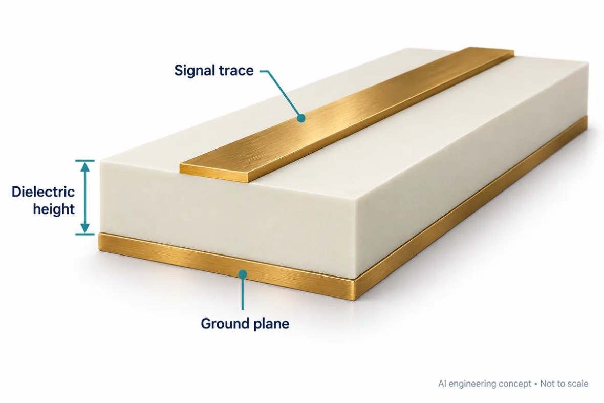
Design workflow: from Dk to a manufacturable line
Begin with the distance from the RF trace to its reference plane, not the total finished-board thickness. Enter that dielectric height in millimetres and choose the dielectric constant appropriate to the confirmed material model. In target mode, the calculator solves a width for the requested impedance. In analysis mode, it estimates impedance from a width you enter. Change one assumption at a time to understand which dimensions are sensitive before committing the layout.
The solver uses a zero-copper-thickness Hammerstad–Jensen quasi-static microstrip approximation. It represents an isolated, uncoated trace over a continuous ground plane. It does not include solder mask, finite copper thickness, roughness, frequency dispersion, neighboring traces, coplanar grounds, via fences or connector launches. Frequency changes the wavelength output, while this model’s impedance remains quasi-static. A production field solver and a fabricator-approved stackup are needed for final controlled-impedance dimensions.
Use the delay and quarter-wavelength outputs as early electrical-length estimates. They do not replace a filter or antenna simulation. Resonant structures also respond to discontinuities, fringing fields, enclosure proximity and fabrication tolerance. For a sensitivity check, vary dielectric height and Dk over the confirmed tolerances and compare the resulting trace widths. Keep those ranges with the drawing instead of reporting a calculated width with unrealistic manufacturing precision.
Plan the stackup as a complete construction
The thickness planner adds the total selected RF dielectric, all other pressed dielectrics and equal copper thickness for each layer. Enter every core, bondply and prepreg contribution exactly once. For two copper layers, the model uses only the RF dielectric and copper. The output excludes solder mask and surface finish. It is a nominal arithmetic budget, not a prediction of resin flow, press shrinkage or an approved multilayer construction.
Before fabrication, ask for the actual layer sequence, material identifiers, pressed dielectric thicknesses, copper weights and tolerances. Review whether reference planes remain continuous beneath critical routes. Identify any blind, buried or through-hole transitions that need separate electrical or reliability evaluation. A total thickness that fits a connector does not by itself establish impedance, bond compatibility or layer balance. Review those requirements together with the proposed manufacturing process.
Cost and quotation: expose the assumptions
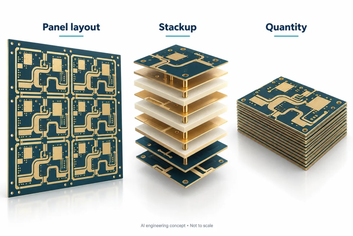
A useful early budget shows what drives the number. Board outline, usable panel size, spacing, ordered quantity and expected yield determine how many full panels the example allocates. The calculator compares a uniform zero-degree layout with a uniform ninety-degree layout and uses the better result. It does not perform mixed-orientation nesting, optimize irregular outlines or reserve tooling rails and coupons automatically. Enter the usable area after those manufacturing reservations.
Material cost is the amount allocated to all laminate in one usable panel. Fabrication cost applies to every board position started on the allocated panels, while testing cost applies to the ordered quantity. Setup is added once. These assumptions deliberately remain visible and editable. The displayed dollar figure is a scenario based on your inputs, not a live supplier price, availability statement or purchasing commitment. Shipping, taxes and assembly are excluded.
For a fair quotation comparison, hold the material grade, foil, stackup, finish, quantity, tolerances and tests constant. A low unit price may cover a different inspection plan or construction. Record any acceptable alternatives explicitly and request approval before substitution. Compare prototype and production quantities separately because setup allocation and panel utilization can change the effective unit cost. Enter confirmed supplier rates when available and rebuild the summary after changing the design.
What a complete RFQ should include
Send the fabrication data, NC drill, board outline and revision together with a layer-by-layer stackup. Include the manufacturer and exact laminate grade, dielectric thickness and tolerance, copper type, finished copper, finish and material substitution restrictions. Identify controlled-impedance nets and target tolerances. State whether the project also needs insertion loss, return loss, phase or other RF acceptance measurements, because these are separate deliverables with their own fixtures and coupons.
Specify the order quantity, panel preferences, delivery destination and required schedule. If the design is still evolving, identify which dimensions or materials remain open to engineering review. The summary button below collects valid calculator scenarios into editable text; it does not transmit your design or submit an order. Review that text, attach the actual manufacturing package and use the quotation form for a build-specific response.
PTFE / Teflon PCB questions
Are PTFE PCB and Teflon PCB interchangeable terms?
PTFE is a generic polymer description. Teflon is a Chemours brand. Search usage overlaps, but branded resin provenance should be verified before making a Teflon material claim.
Is PTFE always the best RF PCB material?
No. Compare the actual loss, phase, geometry, thermal and manufacturing requirements. A qualified thermoset construction may meet some designs; others benefit from a specific PTFE composite.
Is the online cost result a formal quotation?
No. It uses editable illustrative rates and a simplified panel model. A formal quotation requires the fabrication files, exact material construction, testing, quantity and delivery requirements.
Can I manufacture the calculated trace width directly?
Use it as an initial estimate. The model excludes finite copper thickness, mask and other production details. Agree final dimensions and tolerance with the fabricator using the approved stackup and appropriate field solver.
Compare related material choices
Continue the selection using the pages most relevant to the alternative construction: Rogers RO3003 PCB, RT/duroid 5880 PCB, Taconic PCB, Wangling F4B PCB, RF PCB Material Selection Guide. For thermoset RF alternatives, review RO4003C PCB and RO4350B PCB with their own design data and manufacturing requirements.
Material sources and scope
- Rogers explanation of RF laminate compositions
- Chemours Teflon trademark licensing
- Rogers RT/duroid 5880 product data
Manufacturer references support the material facts above. Engineering guidance and calculator scenarios are preliminary aids. No stock, lead time, certification, substitution or RF acceptance result is implied by the illustrations or example calculations.
Turn your PTFE / Teflon PCB design into a clear RFQ
Use the button below to collect the current valid calculator scenarios into editable enquiry text. Attach your manufacturing files separately and review the assumptions before submitting. No calculator input is sent by this button.
- Gerber or agreed fabrication data, NC drill, outline and revision.
- Board quantity, panel requirements and delivery destination.
- Layer-by-layer stackup, material restrictions and copper requirements.
- Target impedance, tolerances, surface finish and test expectations.
- Required lead time and any acceptable engineering alternatives.
Ready for a quotation?
Send your requirements for a material, stackup and manufacturing review. Price and schedule are confirmed for your project.