
Manage current and heat together.
Heavy copper can reduce conductor resistance and spread heat, but a thermal PCB must also provide a complete path from the component to the cooling environment. Review the electrical, mechanical and assembly constraints as one system.
Heavy copper can reduce conductor resistance and spread heat, but a thermal PCB must also provide a complete path from the component to the cooling environment. Review the electrical, mechanical and assembly constraints as one system. Review the build-specific requirements below and use the interactive tool to prepare better engineering questions.
Heavy copper is one part of a thermal design
Increasing copper cross-section reduces the DC resistance of an otherwise identical conductor. More copper can also help spread heat laterally. Neither fact establishes the allowable current of a finished board by itself. Temperature rise depends on geometry, heat sources, neighboring copper, dielectric, airflow, enclosure and connections to a heatsink or chassis.
For an RF power amplifier, bias-current routing and the RF transmission structure may have different priorities. A thick power conductor may be useful for DC distribution while a sensitive microwave trace needs controlled geometry and a suitable surface profile. Avoid applying the same copper assumption to every part of the board without checking its electrical role.
Define base copper and finished copper
Copper weight is often used as a convenient nominal specification, but fabrication drawings should explain whether a value describes base foil or finished conductor thickness. Outer-layer plating and etching affect the final cross-section. Heavy copper also changes the relationship between achievable line spacing, etched profile, solder-mask coverage and resin filling.
The shared rigid-board capability table separates ordinary production and extended prototype copper ranges. Those ranges do not guarantee that the highest copper weight can be combined with the finest spacing, every RF laminate or every via structure. Submit the geometry and current distribution for a specific review through the capabilities team.
Three views of the engineering decision
Copper DC resistance and heating estimate
Estimate a uniform copper trace at an assumed conductor temperature. This does not determine current capacity or temperature rise.
R = ρL/A; ρ20 = 1.724 × 10⁻⁸ Ω·m, α = 0.00393/°C; V = IR; P = I²R. Bulk-copper approximation. Contacts, vias, etch profile, skin effect and cooling are excluded.
Build a complete heat-flow path
Document the heat-producing component, dissipated power, contact area and temperature constraints. Identify how heat reaches copper planes, thermal vias, a spreader, an interface material and the final cooling surface. The dielectric’s thermal conductivity is only one part of that path; contact resistance and spreading effects can dominate.
Thermal vias need a fabrication and assembly definition. Open vias, plugged vias, resin-filled vias and capped structures behave differently in soldering and mechanical integration. A metal-backed or locally inserted structure requires its own review. Do not substitute a simple count of vias for a thermal model, and do not treat a laminate conductivity value measured by one method as directly comparable to a composite-board value.
What the DC estimator can and cannot show
The tool below estimates resistance for a uniform rectangular copper conductor at a stated conductor temperature. It then calculates voltage drop and Joule heating for the entered DC current. It uses nominal copper resistivity and a linear temperature coefficient; it is intended for transparent comparisons between dimensions.
It does not calculate temperature rise, maximum current, skin effect, proximity effect, contact resistance, via loss or RF insertion loss. A temperature entered in the form is an assumption, not a prediction. Use a thermal analysis and appropriate prototype measurements to establish an operating limit. For RF finish effects, continue to surface finish selection.
What the manufacturing review needs
| Review area | Define in your package | Confirm before release |
|---|---|---|
| Copper | Base foil and finished conductor target | Layer-specific thickness and etched geometry |
| Electrical load | DC current, duty cycle and waveform | Voltage-drop and current-distribution limits |
| Thermal load | Power dissipation and boundary conditions | Ambient, heatsink and interface constraints |
| Verification | Thermal model and test setup | Sensor location, steady-state criteria and margin |
These are review requirements, not universal capability limits. The order-specific drawing, process window and acceptance plan control the build.
Prepare a quotation that engineering can review
A useful RF PCB quotation starts with a controlled design package. Send Gerber or an agreed manufacturing format, NC drill data, a dimensioned outline, the board revision and a stackup drawing. Add quantity, delivery destination and the requested schedule. If some details are still open, mark them explicitly instead of letting a drawing, an email and a file name imply different requirements.
Separate mandatory requirements from preferences. A specified laminate, a customer-approved alternative and a request for a recommendation are three different purchasing instructions. State whether the supplier may propose changes to dielectric thickness, line geometry, panelization or finish, and who approves those changes. Changes that affect RF behavior should return to the design owner before release.
What affects the price?
Board area and panel utilization, quantity, material availability, stackup complexity, drilling and plating, special mechanical features, inspection and test all influence cost. Tight tolerances can also change the achievable yield and process route. An online estimate cannot account for every interaction in an unusual construction.
Use the panel and material cost tool to explore the assumptions it exposes, then request a reviewed quotation. Confirm tooling or setup charges, engineering changes, shipping, taxes and the included report package in the commercial offer.
What affects delivery?
Material stock, engineering clarification, special tooling, lamination cycles and the agreed inspection plan can affect the schedule. Assembly adds component procurement, stencil preparation, programming and fixture readiness. The requested date is a planning input until the supplier confirms the complete order scope.
The website’s response-time target describes enquiry handling. It is not a guarantee that a complex RF build can be priced, fabricated or delivered within the same period. Ask the team to identify the critical dependencies for your project.
From review to repeatable production
Agree the build
Engineering reviews material, geometry, mechanical features and test requirements. Open questions and proposed changes are documented. The approved drawing and stackup become the manufacturing baseline.
Verify the first build
Define which records are needed for the prototype: electrical test, impedance, dimensional inspection, cross-sections or an agreed RF measurement. Evaluate the evidence against the relevant acceptance criteria.
Control later changes
Keep revision, material substitutions, process changes and test updates traceable. A successful prototype is the starting point for production control, not permission to change the construction silently.
For a performance issue, retain the board revision, lot reference, measurement setup and operating conditions. Comparing repeatable measurements is more useful than comparing screenshots taken with different fixtures or calibration. Define the investigation and disposition with the supplier using the actual order requirements.
Is your heavy copper thermal PCB package ready?
Select what is ready. This checklist runs locally and does not upload files or place an order.
The factory behind the engineering review
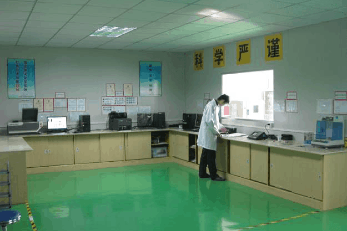
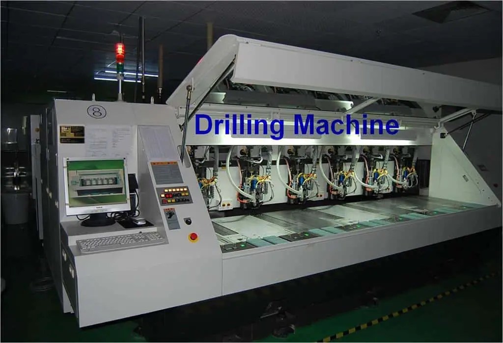
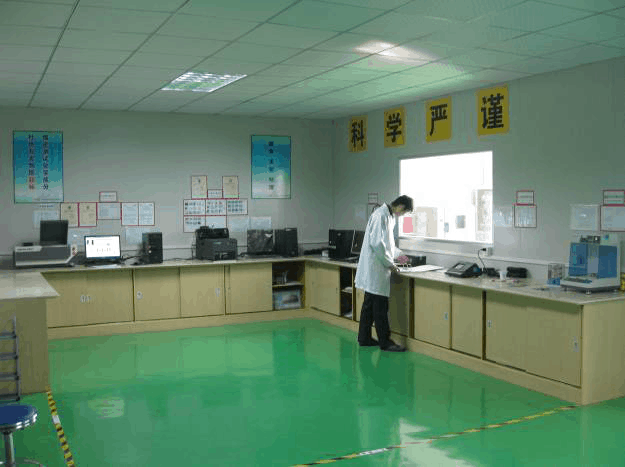
Use real process and laboratory evidence when qualifying a supplier. The photographs below come from the shared RFPCB / PCBSync facility archive. Discuss the equipment and inspection records relevant to your order through our quality page.

Heavy Copper & Thermal PCB Engineering: common questions
Does doubling copper thickness double current capacity?
No. Resistance changes with cross-section, but allowable current depends on the full thermal environment and acceptance temperature.
Does the calculator predict temperature rise?
No. It calculates DC resistance, voltage drop and power at the temperature you enter.
Can heavy copper be combined with RF laminates?
It may be feasible, but material, foil, line geometry, bonding and thermal architecture require a specific manufacturing review.
Continue the engineering review
High Frequency PCB Manufacturing
High frequency PCB manufacturing combines a suitable laminate with controlled geometry, return paths and an agreed test plan. Start with the operating band, loss budget and assembly environment, then choose a construction the factory can repeat.
Surface Finishes for RF PCB
An RF PCB surface finish must support soldering, handling and the intended electrical performance. Compare ENIG, immersion silver, OSP and other finishes using the actual circuit geometry and assembly requirements.
RF PCB Assembly & Test
RF PCB assembly connects bare-board fabrication, component sourcing, soldering and a defined test scope. Provide a controlled BOM, placement data and the RF acceptance conditions so the finished assembly can be evaluated meaningfully.
Technical references and manufacturing scope
The engineering explanations distinguish ideal estimates from production acceptance. Use current material data and the approved drawing for the actual build. RFPCB and PCBSync share a manufacturing operation; the shared factory overview and rigid-board capability table provide context, while specific combinations require review.
- Rogers engineering tools and material calculations
- Rogers: RO4000 / FR-4 hybrid flatness
- Rogers: circuit materials and high-frequency losses
- Texas Instruments: AFE79xx layout and via-transition guidance
Engineering guide updated September 2026. Schematics illustrate concepts and are not fabrication-ready drawings. Product and material names belong to their respective owners.
Send the construction, not just the keyword.
Share your board revision, stackup, quantity and the requirements that matter. The team can identify open questions and confirm the manufacturing and test scope before quoting.
Ready for a quotation?
Send your requirements for a material, stackup and manufacturing review. Price and schedule are confirmed for your project.