
Keep every channel on the same design baseline.
A phased array PCB integrates repeated RF channels, radiating elements and control. Element pitch, channel matching, thermal behavior and calibration must be considered together for communication and sensing arrays.
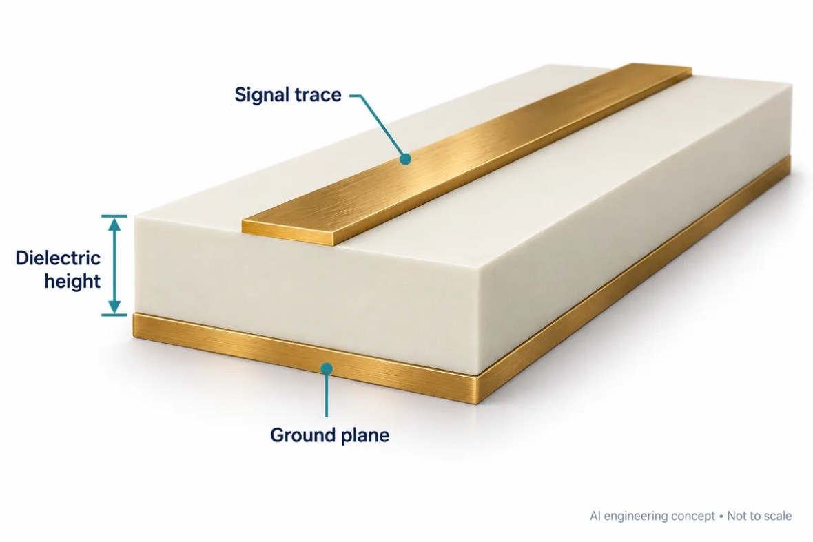
A phased array PCB integrates repeated RF channels, radiating elements and control. Element pitch, channel matching, thermal behavior and calibration must be considered together for communication and sensing arrays. Use the application-specific review below to identify the information needed for material selection, fabrication and acceptance.
A repeated structure needs controlled variation
An electronically steered array combines signals from multiple elements with controlled phase and amplitude. The PCB may carry radiators, feed networks, beamforming devices or a combination of these functions. Repeating the same artwork does not guarantee that every manufactured and assembled channel behaves identically.
Identify the array geometry, operating band, scan requirement and channel architecture. State which matching requirements are electrical and which are geometric. A route-length tolerance can be useful, but the final channel response also includes material variation, devices, connectors, soldering and temperature. Define the calibration strategy as part of the product architecture.
Element pitch and scan coverage are related
For an ideal uniform linear array, spacing between elements affects where grating lobes can appear as the beam is scanned. The simple spacing bound in the tool below uses free-space wavelength and a symmetric scan limit. It is an educational screening relationship, not a complete planar-array or antenna-pattern analysis.
Evaluate the highest frequency of the required band when considering a fixed physical pitch, and account for the real element pattern, mutual coupling and array geometry. Wideband systems can also experience beam squint when steering relies on phase shifts. A compliant pitch bound by itself does not establish sidelobe level, gain, scan loss or polarization quality.
Understand the application interfaces
Uniform linear-array pitch reference
Estimate an ideal spacing bound for a symmetric scan envelope. Use the highest operating frequency when reviewing fixed pitch.
Reference bound d = λ0 / (1 + sin θmax). Equality is the ideal horizon boundary; practical design needs margin. Uniform linear array in free space; no element pattern, coupling, planar geometry or beam-squint model.
Define the RF channel and thermal architecture
Map each channel through the device, routing, transition and radiator. Keep the material construction and intended reference planes explicit. Review how bias, digital control and thermal paths share the available area. Repeated components and narrow pitch can create placement, routing, heat-removal and inspection constraints.
Use the multilayer RF review to define the layer functions and the impedance review for controlled routes. If channels traverse different local geometries, equal drawn lengths may not mean equal electrical lengths. Temperature gradients can also change relative response and should be represented in the validation plan where relevant.
Measure channel matching and array behavior
Plan how individual channels will be accessed and compared. Identify fixture repeatability, reference planes, calibration state, device settings and the conditions for amplitude and phase measurements. A test that combines several channels may hide the source of a local error, so choose evidence appropriate to the stage of development.
Array-level verification should address the required directions, frequencies and polarization, with the intended mechanical environment. Keep calibration files, board revisions and firmware versions traceable. The manufacturing acceptance plan can support consistent construction, but it should not be confused with a guaranteed system beam pattern or a universal phase-matching specification.
Application-to-manufacturing review
| Area | Define for the application | Confirm before release |
|---|---|---|
| Array definition | Element geometry, pitch and frequency range | Scan envelope and architecture |
| Channels | Routing, references and component placement | Amplitude/phase budget and calibration |
| Thermal integration | Power distribution and heat-flow path | Temperature range and gradients |
| Validation | Channel and array test procedures | Fixture, calibration state and traceability |
Connect these requirements to the Multilayer RF PCB Manufacturing workflow. The approved stackup, drawing and order-specific acceptance plan define the build.
Build the acceptance plan around the application
Decide what the bare board must demonstrate and what belongs to the assembled product. Continuity testing, an impedance coupon, a calibrated RF network measurement and an installed-system test are different forms of evidence. None should silently stand in for another. Identify the required report, coverage, limits and review responsibility before the quotation is accepted.
Record the test configuration alongside the result: board revision, material construction, fixture, calibration, firmware or device settings, temperature and the relevant operating point. When comparing prototypes, keep these conditions consistent or explain the difference. A changed connector, cable or reference plane can make an apparent board improvement difficult to interpret.
For production, agree how first-article findings become controlled manufacturing requirements. Identify which dimensions and material choices are critical, what may be adjusted by engineering, and which changes require renewed validation. A repeat order should reference the approved revision and test plan rather than rely on a previous email description.
Visit quality and test evidence for supplier qualification and reporting questions. Where a customer program requires certificates or sector-specific approval, request the actual documents and applicable scope. An application example is not a product certification or a substitute for the customer’s acceptance process.
Prepare a quotation that engineering can review
A useful RF PCB quotation starts with a controlled design package. Send Gerber or an agreed manufacturing format, NC drill data, a dimensioned outline, the board revision and a stackup drawing. Add quantity, delivery destination and the requested schedule. If some details are still open, mark them explicitly instead of letting a drawing, an email and a file name imply different requirements.
Separate mandatory requirements from preferences. A specified laminate, a customer-approved alternative and a request for a recommendation are three different purchasing instructions. State whether the supplier may propose changes to dielectric thickness, line geometry, panelization or finish, and who approves those changes. Changes that affect RF behavior should return to the design owner before release.
What affects the price?
Board area and panel utilization, quantity, material availability, stackup complexity, drilling and plating, special mechanical features, inspection and test all influence cost. Tight tolerances can also change the achievable yield and process route. An online estimate cannot account for every interaction in an unusual construction.
Use the panel and material cost tool to explore the assumptions it exposes, then request a reviewed quotation. Confirm tooling or setup charges, engineering changes, shipping, taxes and the included report package in the commercial offer.
What affects delivery?
Material stock, engineering clarification, special tooling, lamination cycles and the agreed inspection plan can affect the schedule. Assembly adds component procurement, stencil preparation, programming and fixture readiness. The requested date is a planning input until the supplier confirms the complete order scope.
The website’s response-time target describes enquiry handling. It is not a guarantee that a complex RF build can be priced, fabricated or delivered within the same period. Ask the team to identify the critical dependencies for your project.
From review to repeatable production
Agree the build
Engineering reviews material, geometry, mechanical features and test requirements. Open questions and proposed changes are documented. The approved drawing and stackup become the manufacturing baseline.
Verify the first build
Define which records are needed for the prototype: electrical test, impedance, dimensional inspection, cross-sections or an agreed RF measurement. Evaluate the evidence against the relevant acceptance criteria.
Control later changes
Keep revision, material substitutions, process changes and test updates traceable. A successful prototype is the starting point for production control, not permission to change the construction silently.
For a performance issue, retain the board revision, lot reference, measurement setup and operating conditions. Comparing repeatable measurements is more useful than comparing screenshots taken with different fixtures or calibration. Define the investigation and disposition with the supplier using the actual order requirements.
Prepare your phased array PCB enquiry
Select what is ready. This checklist runs locally and does not upload files or place an order.
Real manufacturing and laboratory context
These photographs are from the shared RFPCB / PCBSync facility archive. They show manufacturing and laboratory areas, not a claim that a pictured item is a certified phased array PCB product. Review the actual process and report requirements with the team.



Phased Array PCB Design & Manufacturing: common questions
Does half-wavelength spacing guarantee the required beam pattern?
No. It addresses an ideal spacing condition; element pattern, coupling, tapering, geometry and calibration still matter.
Are equal trace lengths enough for phase matching?
No. Electrical length also depends on material, geometry, transitions and operating conditions.
Does the pitch tool model a full planar array?
No. It uses an ideal uniform linear-array bound. A real array needs electromagnetic and system-level evaluation.
Related application decisions
Antenna PCB Design & Manufacturing
An antenna PCB must preserve the radiator geometry, feed network and surrounding electromagnetic environment. Review the laminate, reference planes, enclosure and measurement method together before manufacturing.
5G & mmWave PCB Manufacturing
A 5G or millimeter-wave PCB brings RF interconnects, antenna structures and digital control into a tightly coupled design. Select the stackup around the actual operating band and bandwidth rather than the 5G label alone.
Satcom & Aerospace RF PCB Manufacturing
Satellite communication and aerospace RF boards span ground terminals, airborne equipment and spacecraft hardware. These environments have different requirements; the manufacturing and qualification scope must identify the actual end use.
Technical references and scope
Use current component and material documentation together with the approved design. The sources below provide engineering context; the specific product and manufacturing acceptance requirements remain project-dependent.
- Analog Devices: grating lobes and beam squint
- RFPCB material selection and engineering tools
- Manufacturing capability review
Engineering guide updated September 2026. Diagrams are conceptual and not production drawings. Calculations are estimates under the stated assumptions.
Bring the application requirements into the quote.
Send the operating band, board revision, stackup, quantity and acceptance needs. The team can identify missing information and review the proposed manufacturing scope.
Ready for a quotation?
Send your requirements for a material, stackup and manufacturing review. Price and schedule are confirmed for your project.