
Start with a clear layer-function map.
Explore four concept stackups, inspect the dielectric and copper schedule, and copy a nominal thickness summary. Use the example as a discussion document before the factory confirms a manufacturable construction.
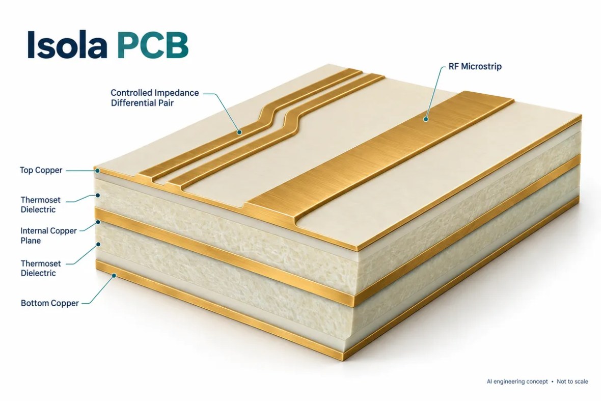
Explore a concept stackup
These are educational starting points, not prequalified or stocked stackups. Select a concept and update the uniform copper assumption to see the nominal thickness budget.
Total = sum of dielectric regions + layer count × copper µm / 1000. No solder mask, finish, plating variation, resin-flow prediction or tolerance accumulation is included. Cured dimensions and material availability require approval.
All four concepts at a glance
2-layer RF evaluation board
RF signal / component side → Ground reference
Dielectric regions (mm): 0.508.
A simple outer-layer RF route over a ground plane. Total includes two nominal 35 µm copper layers; it is not a stock-item specification.
4-layer RF + control concept
RF signal → Ground reference → Power / control → General signal
Dielectric regions (mm): 0.203, 0.914, 0.203.
Assign the bonding construction and reference for every controlled net. Listed regions do not imply interchangeable prepreg systems.
6-layer symmetric RF-surface concept
RF signal / components → Ground reference → Digital signal → Power distribution → Ground reference → RF signal / components
Dielectric regions (mm): 0.203, 0.2, 0.584, 0.2, 0.203.
Geometrically symmetric thickness proposal, not a guarantee of copper balance or bow/twist. Name all core and bonding materials.
8-layer mixed RF / digital concept
RF signal → Ground reference → Digital signal → Ground reference → Power distribution → Digital signal → Ground reference → RF signal
Dielectric regions (mm): 0.127, 0.2, 0.2, 0.266, 0.2, 0.2, 0.127.
Review the manufacturing sequence, power integrity, return paths and every transition. These dimensions are illustrative nominal cured values.
What a stackup library should provide
A useful stackup reference identifies the purpose of each conductive layer and the dielectric regions between them. It should make assumptions visible rather than imply that a familiar layer count is a complete manufacturing specification. The examples here are conceptual arrangements with illustrative nominal cured thicknesses.
These examples are not a catalog of stocked constructions, prequalified material combinations or promised impedance values. No particular bondply is silently assigned to a generic bonding region. Ask the fabricator to identify the actual core, prepreg or bondply, resin content where relevant, foil option and process sequence before releasing a drawing.
Choose layer functions around the signal path
Map RF routes to nearby reference planes and identify where signals change layers. Assign digital, clock, power and ground functions deliberately. A layer labeled ground does not guarantee an unbroken return path if the actual artwork has slots or discontinuities in the relevant area.
A two-layer evaluation board can be a useful starting architecture for a simple exposed RF line, while a more integrated design may need additional routing and power layers. More layers are not automatically better. The multilayer RF review helps evaluate the architecture, transitions and manufacturing sequence together.
Nominal thickness is not the press recipe
The tool sums the entered concept’s dielectric regions and a uniform copper-thickness assumption. This is an accounting check, not a prediction of cured resin flow, etch profile, plated thickness or manufacturing variation. Mask and finish are intentionally excluded from the displayed sum.
A real stackup may have different copper thicknesses on different layers and material regions whose cured dimensions depend on the construction. Use the custom thickness budget for another initial check, then obtain the manufacturer’s layer-specific drawing. Confirm whether the mechanical requirement refers to a particular finished-board measurement condition.
Review bonding, balance and transitions
A symmetric thickness drawing can help organize a review but does not guarantee balanced copper or flatness. Pattern distribution, materials, cavities, component loading and processing can still affect the result. For mixed materials, use the hybrid construction review to define compatibility and the bonding system.
Specify via layer spans, pad and antipad requirements, any filling or capping, and back-drill details where relevant. The stackup must support the intended hole architecture. A generic diagram copied from another supplier may need changes for material availability and processing. Keep every approved change connected to the electrical model and board revision.
Keep the engineering assumptions connected
Build the acceptance plan around the application
Decide what the bare board must demonstrate and what belongs to the assembled product. Continuity testing, an impedance coupon, a calibrated RF network measurement and an installed-system test are different forms of evidence. None should silently stand in for another. Identify the required report, coverage, limits and review responsibility before the quotation is accepted.
Record the test configuration alongside the result: board revision, material construction, fixture, calibration, firmware or device settings, temperature and the relevant operating point. When comparing prototypes, keep these conditions consistent or explain the difference. A changed connector, cable or reference plane can make an apparent board improvement difficult to interpret.
For production, agree how first-article findings become controlled manufacturing requirements. Identify which dimensions and material choices are critical, what may be adjusted by engineering, and which changes require renewed validation. A repeat order should reference the approved revision and test plan rather than rely on a previous email description.
Visit quality and test evidence for supplier qualification and reporting questions. Where a customer program requires certificates or sector-specific approval, request the actual documents and applicable scope. An application example is not a product certification or a substitute for the customer’s acceptance process.
Prepare a quotation that engineering can review
A useful RF PCB quotation starts with a controlled design package. Send Gerber or an agreed manufacturing format, NC drill data, a dimensioned outline, the board revision and a stackup drawing. Add quantity, delivery destination and the requested schedule. If some details are still open, mark them explicitly instead of letting a drawing, an email and a file name imply different requirements.
Separate mandatory requirements from preferences. A specified laminate, a customer-approved alternative and a request for a recommendation are three different purchasing instructions. State whether the supplier may propose changes to dielectric thickness, line geometry, panelization or finish, and who approves those changes. Changes that affect RF behavior should return to the design owner before release.
What affects the price?
Board area and panel utilization, quantity, material availability, stackup complexity, drilling and plating, special mechanical features, inspection and test all influence cost. Tight tolerances can also change the achievable yield and process route. An online estimate cannot account for every interaction in an unusual construction.
Use the panel and material cost tool to explore the assumptions it exposes, then request a reviewed quotation. Confirm tooling or setup charges, engineering changes, shipping, taxes and the included report package in the commercial offer.
What affects delivery?
Material stock, engineering clarification, special tooling, lamination cycles and the agreed inspection plan can affect the schedule. Assembly adds component procurement, stencil preparation, programming and fixture readiness. The requested date is a planning input until the supplier confirms the complete order scope.
The website’s response-time target describes enquiry handling. It is not a guarantee that a complex RF build can be priced, fabricated or delivered within the same period. Ask the team to identify the critical dependencies for your project.
From review to repeatable production
Agree the build
Engineering reviews material, geometry, mechanical features and test requirements. Open questions and proposed changes are documented. The approved drawing and stackup become the manufacturing baseline.
Verify the first build
Define which records are needed for the prototype: electrical test, impedance, dimensional inspection, cross-sections or an agreed RF measurement. Evaluate the evidence against the relevant acceptance criteria.
Control later changes
Keep revision, material substitutions, process changes and test updates traceable. A successful prototype is the starting point for production control, not permission to change the construction silently.
For a performance issue, retain the board revision, lot reference, measurement setup and operating conditions. Comparing repeatable measurements is more useful than comparing screenshots taken with different fixtures or calibration. Define the investigation and disposition with the supplier using the actual order requirements.
Prepare an engineering review from this resource
Select what is ready. This checklist runs locally and does not upload files or place an order.
From an online result to a manufactured board
RFPCB and PCBSync share a manufacturing operation. The photographs below show real process and laboratory areas from that facility archive. An online calculation is an engineering aid; a quotation and acceptance plan still need the actual design package.



RF PCB Stackup Library — 2, 4, 6 & 8 Layers: common questions
Are these stackups available to order unchanged?
No. They are educational concepts; exact materials, dimensions, process capability and availability must be confirmed.
Does the total include solder mask and finish?
No. The displayed budget sums dielectric regions and the uniform copper assumption only.
Does a symmetric diagram guarantee low bow and twist?
No. Copper patterns, material behavior and processing also matter. Flatness requirements need a build-specific review.
Related RF design resources
PCB Impedance Calculator — Microstrip & Width Solver · RF PCB Insertion Loss Calculator & Budget · RF PCB Dk / Df Comparison Table · RF PCB Material Cross-Reference & Candidate Tool · RF PCB Stackup Library — 2, 4, 6 & 8 Layers · RF PCB Design Guide & Review Checklist
Continue with controlled impedance manufacturing, hybrid stackup review or a project enquiry when your assumptions are ready for engineering review.
Model and data sources
- Qucs technical documentation: microstrip model and loss equations
- Rogers RO4003C / RO4350B datasheet
- Rogers RO3000 datasheet, January 2024
Sources reviewed September 2026. Original supplier documents control their stated values and conditions. Educational stackups and calculations are not manufacturing approvals. The page explains the model scope rather than claiming full-wave accuracy or material equivalence.
Send the assumptions with the design.
Include the model, material source, stackup, geometry and acceptance needs. The engineering team can review open questions and confirm a quotation scope.
Ready for a quotation?
Send your requirements for a material, stackup and manufacturing review. Price and schedule are confirmed for your project.