
Material comparison · Engineering selection
RO4350B vs RO4003C is a choice between two related RF thermoset laminates with different electrical references and flame-rating characteristics. Compare the complete PCB construction, then test how a change in effective permittivity could affect a resonant circuit.
Choose neither material by brand familiarity alone. RO4350B is a candidate where its laminate flame rating matters; RO4003C is a candidate where its electrical properties and non-flame-retardant formulation meet the product requirements. A change of grade still needs stackup, impedance, circuit and compliance review.
RO4350B and RO4003C reference comparison
| Decision | RO4350B | RO4003C |
|---|---|---|
| Material family | Glass-reinforced hydrocarbon/ceramic thermoset | Glass-reinforced hydrocarbon/ceramic thermoset |
| Typical process Dk | 3.48 ± 0.05 | 3.38 ± 0.05 |
| Published design Dk | 3.66 | 3.55 |
| Typical Df at 10 GHz | 0.0037 | 0.0027 |
| Laminate flammability | UL 94 V-0 reference; verify exact construction | Non-FR formulation |
| Selection consequence | Check rating, loss and exact foil/thickness | Check product requirements before substitution |
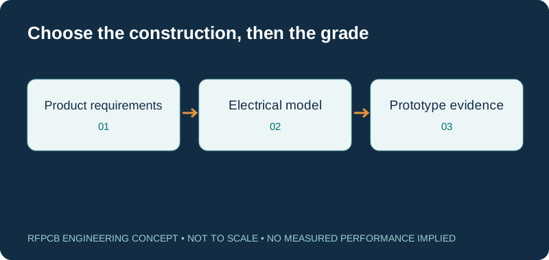
Resonance sensitivity explorer
f₂ = f₁ × (L₁/L₂) × √(εeff₁/εeff₂). Hold geometry and coupling assumptions consistent. These are effective permittivities from a transmission-line model, not automatically the published bulk or process Dk. The calculation illustrates sensitivity rather than synthesizing a filter.
What changes when you swap the material?
A material substitution changes the electrical model underneath the artwork. A line that had the intended impedance on one construction may move away from that target when dielectric properties, core thickness or copper profile change. A resonator can shift even when its dimensions remain identical. Treat “same thickness” as only one constraint in a larger comparison, not as evidence that the two boards will behave alike.
The useful question is therefore whether the alternative construction meets the same measured acceptance criteria. Identify which features are sensitive: feed lines, coupled sections, matching networks, connector launches and transitions between layers. Reuse of a previously validated layout is a project decision that needs evidence.
Use process Dk and design Dk for their intended purposes
Process Dk and design Dk are not two frequency modes that you switch at an arbitrary threshold. They reflect different characterization and modeling conventions. Keep the test method alongside every value used in a comparison. For a field solver, start with the material model appropriate to the proposed construction, then correlate that model with the structures that matter to your circuit.
The interactive calculation above deliberately requests effective permittivity. That is the value seen by a particular transmission structure, including the influence of its geometry. Do not copy bulk Dk into this field and interpret the resulting resonance as an approved prediction.
Read the loss figures without overpromising insertion loss
The material Df reference does not describe total connector-to-connector insertion loss. Conductor roughness, copper thickness, surface finish, mismatch, radiation and transitions can all contribute. A short path with several launches can be dominated by different mechanisms from a long uniform line. Compare an actual route or representative coupon using a consistent simulation and measurement method.
If lower loss is the reason for changing material, state the frequency band and allowable loss in the RFQ. Specify the reference planes and whether connectors are included. Otherwise two technically accurate measurements can answer different questions and appear to disagree.
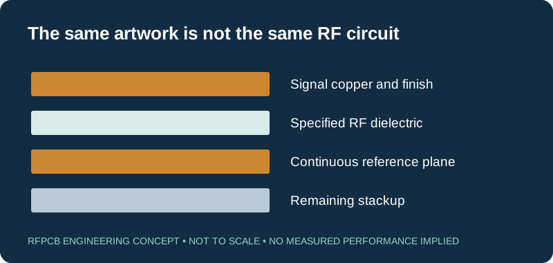
Flame rating belongs in the product requirements
First establish whether the end product requires a particular recognized material construction. A laminate rating is not a blanket certification for every PCB and assembly made from that laminate. Thickness, copper configuration and the completed product requirements must be considered by the responsible engineering and compliance teams.
Purchasing should not approve an electrically attractive alternative until this requirement is resolved. Record the exact manufacturer designation on the approved bill of materials or fabrication drawing. A supplier description such as “Rogers equivalent” does not preserve the evidence associated with a named grade.
Compare fabrication and hybrid-stackup options
Both candidates are used in RF thermoset constructions, but a finished multilayer board still requires a compatible bonding system and an approved press plan. Identify which dielectric regions carry sensitive RF fields and which support digital routing or power distribution. A selective hybrid construction may be worth evaluating before changing the RF material itself.
Use the hybrid stackup guide to prepare a layer-by-layer discussion. Keep copper balance, reference planes and dielectric spacing visible in the drawing. Engineering should confirm the construction before fine impedance-controlled routes are frozen in the layout.
Why a lower laminate price may not lower your project cost
A purchasing comparison should include material allocation, fabrication, setup, inspection, delivery and the cost of qualifying the change. Small orders may be dominated by fixed preparation work. A lower material rate can be offset by a less efficient panel, another processing step or an additional prototype iteration.
The RF PCB cost calculator separates these assumptions so that you can compare one change at a time. Use supplier-confirmed inputs when evaluating a real purchase. Keep demonstration values separate from the commercial quotation and do not treat a calculated difference as a promised saving.
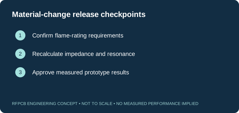
A practical comparison experiment
For an established circuit, preserve the baseline data before ordering a substitute. Record the approved stackup, lot identity, copper and finish, board revision and measurement setup. Define the metrics that would justify the change: insertion loss, return loss, center frequency, bandwidth, temperature behavior or another relevant requirement.
Build a representative sample using the proposed alternative and measure it under the same conditions. If trace width or tuning dimensions change, document those changes rather than describing the exercise as a drop-in test. Keep the revised manufacturing package linked to the resulting evidence.
Choose the next page for your design stage
If you need the fabrication specification for a selected grade, use the dedicated RO4350B PCB guide or RO4003C PCB guide. This comparison page serves the choice between them; it does not replace the manufacturing drawing for either.
For a sensitive resonator, request an agreed dimensional inspection plan as well as a material identity check. For a routed interconnect, use the impedance calculator as an initial geometry aid and obtain construction-specific engineering confirmation before release.
Keep the approval record useful for repeat orders
A successful prototype does not eliminate the need for a controlled production specification. Preserve the accepted grade, dielectric thickness, foil designation, finish and any tuned dimensions. Identify which changes require notification, and distinguish approved alternatives from candidates still under investigation.
When purchasing repeats the order, reference the approved revision rather than attaching a mixture of old and new files. If delivery pressure leads to a proposed substitution, compare it against the same acceptance criteria. This makes the material decision repeatable across engineering, procurement and manufacturing.
Prepare a reviewable engineering request
Check only the requirements you have actually documented. This list records readiness; it does not inspect your files or certify a design. Missing information is useful: identify it explicitly so the engineering review can resolve it before a production release.
These inputs are processed in your browser and are not submitted by this tool. The downloaded summary is a plain-text planning record. Use the secure quote form to send files; request an NDA first if your project requires one.
Manufacturing context
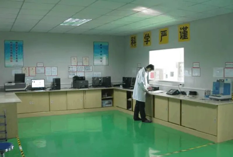
RFPCB and PCBSync share the manufacturing facility shown below. These process photographs illustrate the production environment; they are not evidence that a particular board, material grade or RF performance has been qualified. Request the documentation and inspection scope applicable to your project.


RO4350B vs RO4003C FAQs
Is RO4350B always better than RO4003C?
No. The better choice depends on the circuit, the required material recognition, the available construction and the complete manufacturing cost. Compare measurable requirements rather than treating one grade as a universal upgrade.
Can I use the same Gerber files for both?
You can submit the same files for a feasibility comparison, but that does not establish electrical equivalence. The proposed stackup, line impedance and resonant features must be reviewed before the same artwork is approved for another material.
Does the smaller Df guarantee a lower board insertion loss?
No. Df describes one material loss mechanism under stated conditions. Finished-path loss also depends on copper, finish, geometry, connectors and mismatch. Specify a representative test structure and common measurement reference planes.
Which material is cheaper?
There is no reliable universal finished-board price relationship. Request comparable quotations with the same quantity, thickness, foil, finish and test scope, then include any redesign or qualification cost in the decision.
Continue your engineering review
Compare both constructions with one clear RFQ
Send the operating band, stackup, quantities and required acceptance results. Identify which material is approved and which is an alternative to investigate.
Sources and engineering scope
Manufacturer values apply to the identified grade, test method and construction. Engineering examples on this page are illustrative; they are not measured product results, inventory statements or certification claims. Rogers product names are trademarks of their owner. Keep the applicable datasheet revision with your approved manufacturing package.
Ready for a quotation?
Send your requirements for a material, stackup and manufacturing review. Price and schedule are confirmed for your project.