
RFPCB blog · Material selection explained
Rogers vs FR4 PCB is a design decision about a specific RF path, not a universal ranking of brands. This guide uses Rogers RO4350B as the named RF laminate and explains what must be specified before comparing it with an FR4 construction. Start with the circuit requirement, then compare modeled performance, manufacturing constraints and delivered cost.
Choose the construction that meets the required loss, impedance and repeatability with an acceptable qualification and purchasing scope. RO4350B has published microwave material data, but its name does not guarantee board performance. FR4 can be appropriate when a named grade and controlled construction meet the application. There is no universal frequency cutoff or cost multiplier that decides every project.
RO4350B versus FR4: define both sides of the comparison
| Decision point | Named RO4350B construction | Proposed FR4 construction |
|---|---|---|
| Material identity | Glass-reinforced hydrocarbon/ceramic thermoset | Specify manufacturer, grade, reinforcement and resin construction |
| Dk reference | Process 3.48 ± 0.05 at 10 GHz / 23°C; 4 mil exception applies | Request grade-specific data with method, frequency and construction |
| Design model | Published design Dk 3.66; differential phase-length method, 8–40 GHz | Use the model appropriate to the selected grade and stackup |
| Dielectric loss reference | Typical Df 0.0037 at 10 GHz / 23°C | Do not assign one generic Df value to every FR4 board |
| Finished route loss | Also depends on copper, geometry, finish and transitions | Evaluate the same route boundaries and operating band |
| Cost comparison | Reviewed delivered-board quote plus qualification scope | Equivalent quantity, construction detail and acceptance scope |
| Release evidence | Approved stackup, material identity and representative test plan | The same documentation, including limits on substitution |
Resonance sensitivity explorer
f₂ = f₁ × (L₁/L₂) × √(εeff₁/εeff₂). Hold geometry and coupling assumptions consistent. These are effective permittivities from a transmission-line model, not automatically the published bulk or process Dk. The calculation illustrates sensitivity rather than synthesizing a filter.
Why the grade name matters more than the brand
Rogers supplies multiple material families, so a statement about “Rogers Dk” is incomplete. This article selects RO4350B to make the comparison reviewable. FR4 also needs more definition than its familiar label: the proposed manufacturer's grade, glass style, resin content, thickness and copper should appear in the construction record. A quotation that lists only Rogers versus FR4 has not yet defined two equivalent engineering options.
Use the comparison to answer a concrete question. Perhaps a feed trace consumes too much insertion-loss budget, or a distributed filter moves outside its required band between builds. Those problems need different evidence. Write the symptom, the acceptance threshold and the permitted redesign scope before selecting a replacement. If the present board already meets all requirements, a material change still needs a reason and a proportionate approval plan; a different brand name alone is not an improvement.
Read Dk and Df with their measurement conditions
The RO4000 manufacturer datasheet distinguishes process Dk from design Dk. Its RO4350B table gives process Dk 3.48 ± 0.05 at 10 GHz and a design value of 3.66 derived by a different method. The 4 mil construction has a stated process-Dk exception of 3.33 ± 0.05. Preserve these conditions when entering values in a comparison sheet.
For FR4, ask for equivalent information on the grade actually offered. An unknown value should remain an open question, rather than being filled with a number copied from a generic online table. Also record whether a property is typical, specified or measured on the supplied construction. A material-property tolerance and the finished board's impedance tolerance answer different questions. Keep the applicable datasheet revision with the project so the next reviewer can reproduce the assumptions behind the selection.
Use a sensitivity calculation to reveal a design risk
A resonant feature depends on electrical length, so small changes can matter even when two nominal material values look close. The explorer on this page estimates a frequency shift from effective permittivity and path length. These inputs belong to the chosen transmission-line geometry; published bulk or process Dk is not automatically the effective permittivity of a surface trace. The calculation does not synthesize a filter or predict either material's measured performance.
As an illustrative scenario, hold a 10 mm path constant and change effective permittivity from 3.00 to 3.06. A 10 GHz reference becomes approximately 9.9015 GHz, a decrease of about 0.985%. Neither effective value is assigned here to RO4350B or FR4. Use this result to decide whether your frequency margin warrants more detailed modeling and a representative prototype. Include coupling, end effects and actual dimensions in that later review.
Compare a complete loss budget, not isolated Df numbers
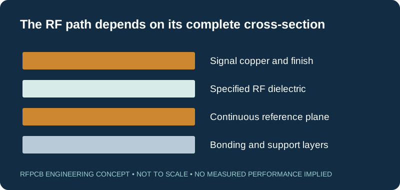
Define where the RF path starts and ends before comparing loss. A connector-to-connector result includes more than the uniform PCB trace. Launches, vias, components and mismatches can influence the measurement. Rogers' article on circuit materials and high-frequency losses discusses the contributions of dielectric, copper profile and surface finish. Its particular test structures do not establish a fixed loss ratio for all RO4350B and FR4 boards.
Prepare a budget at the operating frequencies using comparable models or measurements. If one candidate uses a different trace width, copper foil or launch, record that change explicitly. A finished construction comparison may be useful even when the structures differ, but it cannot isolate the dielectric's contribution. For a worked planning approach, use the RF prototype board guide. Leave enough detail that another engineer can identify what was included in each loss entry.
Decide whether a controlled FR4 construction is sufficient
An RF board does not fail merely because its drawing says FR4. The useful question is whether the proposed construction can meet your electrical and environmental requirements with adequate margin. Short routing, a tolerant circuit and a well-characterized reference design can lead to a different decision from a long feed network or a narrowband distributed structure. Frequency alone does not express route length, permitted attenuation or sensitivity to dimensions.
Ask the design owner to identify the most demanding function and the uncertainty that could change the decision. For example, is the concern a known loss estimate, an unspecified material model, or insufficient evidence from repeat builds? Treat these separately. If the FR4 option has enough documented margin, retain it as a legitimate candidate. If the evidence is incomplete, define a coupon or prototype that resolves the missing point before turning uncertainty into a material prohibition.
Specify the stackup before copying RF artwork
Trace width is only one part of an RF interconnect. The spacing to the reference plane, copper geometry and surrounding dielectric determine the electromagnetic structure. A reference layout transferred to a different stackup therefore needs review even if its outline and component placement look identical. TI's layout review application note explicitly connects reference-design transfer to stackup and dielectric properties.
Mark the RF layers and their reference planes on a layer drawing. Identify controlled dimensions, intended solder-mask treatment and transitions between layers. Decide which parameters can change to meet impedance and which must remain fixed for mechanical or circuit reasons. Give the fabricator permission boundaries rather than an instruction to adjust everything automatically. The returned stackup should resolve the proposed geometry and open questions before fabrication, especially when the same Gerber set is being considered for both material options.
Consider a hybrid only after tracing the fields
A mixed-material board can place a specified RF dielectric near critical circuitry while using other materials elsewhere. Analog Devices' ADRF5345 evaluation-board guide documents one particular construction with RO4350B beneath top-layer RF routing and FR4 elsewhere. That example shows a possible architecture, not a universal stackup recipe, cost saving or approval for another device.
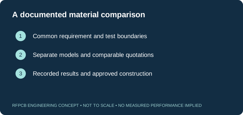
Review a proposed hybrid as a complete multilayer construction. Identify the bonding layers, the reference plane that bounds each RF structure and any via passing through multiple dielectrics. Ask how finished thickness, mechanical balance and assembly requirements will be controlled. Do not assume an RF signal sees only the material named beside its surface layer. The useful comparison is among fully defined all-FR4, hybrid and other appropriate options; the material labels alone do not establish their performance or manufacturability.
Compare delivered cost on the same basis
A universal statement that one material costs a certain number of times another hides the purchasing scope. Request quotations for the same board outline, quantity, layer construction, copper, finish and acceptance requirements. Include setup, material allocation, coupons, inspection and any assembly work. An attractive bare-board figure can become an incomplete comparison if the alternative needs additional engineering or tests that the baseline has already completed.
Record one-time and recurring expenses separately. Use the RF PCB cost worksheet with entered quotations, and the material-change break-even guide when qualification cost matters. Treat delivery dates and availability as quotation-specific information. Request current confirmation instead of assuming stock from a material listing. The commercial decision should explain the delivered scope and remaining risks in terms the purchasing and design teams can both review.
Make the material trial answer one defined question
Choose a representative test structure around the decision you need to make. A simple transmission-line coupon may help evaluate a feed path, while a filter comparison needs the sensitive resonators and coupling geometry represented. Specify the sample identity, artwork revision, measured dimensions and acceptance boundaries. Set the thresholds before receiving results so that a convenient outcome does not silently change the requirement.
If the main question is total delivered performance, test the complete proposed construction and report it that way. If the question is why performance changed, keep other factors consistent where practical and record unavoidable differences. Retain the measurement setup and raw data alongside any processed result. A successful prototype is evidence about that documented build. Decide separately what material identity, production checks and change notification are needed to support repeat orders under the same approval.
Turn the choice into a clear manufacturing request
Finish the review with a short decision record: the selected construction, the requirement it meets, the evidence used and the uncertainties still open. Name the person responsible for approving a material substitution. If an alternative is permitted, describe its specific grade and construction rather than using “equivalent FR4” or “Rogers equivalent” without boundaries. This makes the engineering decision usable after the original designer leaves the project.
For a project review, send the operating band, current stackup, manufacturing data, expected quantities and the acceptance plan. Explain whether unchanged artwork is mandatory or geometry adjustments are allowed. Continue to the RO4350B manufacturing guide for grade-specific context and the RF DFM checklist for package preparation. The output should be a construction-specific proposal and comparable quotation, followed by the agreed evidence for release.
Prepare a reviewable engineering request
Check only the requirements you have actually documented. This list records readiness; it does not inspect your files or certify a design. Missing information is useful: identify it explicitly so the engineering review can resolve it before a production release.
These inputs are processed in your browser and are not submitted by this tool. The downloaded summary is a plain-text planning record. Use the secure quote form to send files; request an NDA first if your project requires one.
Manufacturing context
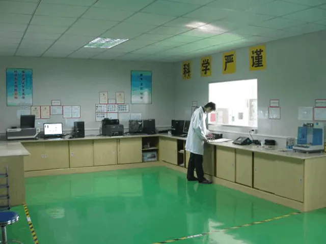
RFPCB and PCBSync share the manufacturing facility shown below. These process photographs illustrate the production environment; they are not evidence that a particular board, material grade or RF performance has been qualified. Request the documentation and inspection scope applicable to your project.


Rogers vs FR4 PCB questions
Is RO4350B always better than FR4?
No. Select against the required electrical margin, construction control and delivered scope. A specified FR4 construction may meet the project, while a sensitive RF path may justify evaluating RO4350B. Neither material name alone proves the finished result.
At what frequency must I stop using FR4?
There is no universal cutoff. Route length, allowable loss, geometry, the actual FR4 grade and the sensitivity of the circuit all matter. Compare candidates over the required band and verify the assumptions that could affect acceptance.
Can I change the laminate without changing the layout?
Only after reviewing the actual stackups and qualifying the result. Identical artwork does not preserve impedance, propagation or resonance when material properties or dielectric spacing change. Record any permitted geometry adjustment before requesting fabrication.
Does the calculator predict the difference between these materials?
No. It uses the effective permittivity and length values you enter in a simplified sensitivity formula. Its defaults are illustrative and are not RO4350B or FR4 test data. Use construction-specific models and measurements for a real decision.
Continue your engineering review
Request a construction-specific material review
Share the RF requirement, named candidate materials, proposed stackup and quantities. Mark fixed geometry and unresolved questions so the response can address the engineering comparison and quotation scope.
Sources and engineering scope
- Rogers: RO4000 laminates manufacturer datasheet, including measurement conditions and 4 mil exception
- Rogers: Circuit Materials and High-Frequency Losses of PCBs
- Texas Instruments: AN098, Layout Review Techniques for Low Power RF Designs
- Analog Devices: EVAL-ADRF5345 user guide, Rev. A, example RF stackup
Manufacturer values apply to the identified grade, test method and construction. Engineering examples on this page are illustrative; they are not measured product results, inventory statements or certification claims. Manufacturer and product names belong to their respective owners. Keep the applicable datasheet revision with your approved manufacturing package.
Put this into production
Request a material, stackup and manufacturing review for your RF PCB project.