
Engineering resources · Evidence and acceptance planning
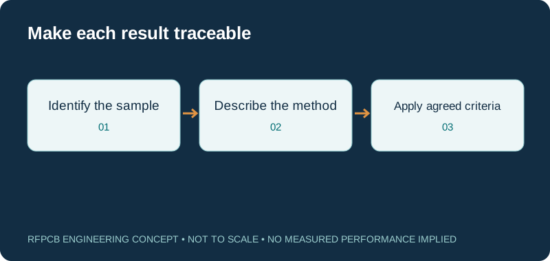
An RF PCB test report should connect each result to a defined sample, method and requirement. A pass label without the measured quantity, conditions and coverage can leave the engineering question unanswered. Request the required evidence before production begins.
Read the sample identity and test scope before the pass column. DC electrical test, TDR, VNA and microsection are complementary records. For RF results, state reference planes and fixture treatment; for a decision near a limit, document the uncertainty information and the agreed decision rule. No generic report proves every aspect of a board.
Minimum context for four different test records
| Report type | Identify in the record | Avoid this unsupported conclusion |
|---|---|---|
| DC electrical test | Board revision, netlist, continuity/isolation conditions and coverage | A passing netlist establishes RF impedance or loss |
| TDR impedance | Sample or coupon, target, rise time, evaluation region and measured values | One coupon proves every transition on every board |
| VNA measurement | Port map, sweep, calibration, reference planes and raw/corrected state | A plot without fixture context is directly comparable |
| Microsection | Physical location, image scale, sample identity and measured features | A local destructive sample inspects the complete delivery |
| Acceptance statement | Requirement revision, uncertainty treatment and decision rule | A calculator or a supplier logo creates contractual acceptance |
Impedance interval and uncertainty explorer
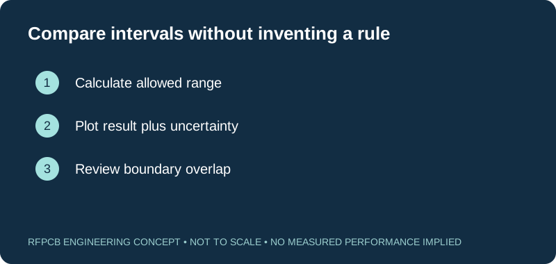
Allowed interval = target × (1 ± tolerance/100). Compare the measurement ± entered expanded uncertainty with that interval. Inside, outside and overlapping are geometric relations, not certification or an agreed conformity decision. Record the coverage factor, confidence assumptions and contractual decision rule separately. Default inputs are illustrative and are not factory results.
Start with the question the report must answer
Before requesting a standard quality pack, write down the concern behind each requested record. Continuity, controlled impedance, transmission loss and local plating dimensions are different quantities. Assign each requirement to a method and identify who reviews the result.
Keep the applicable drawing revision and acceptance criteria with the purchase specification. If a requirement refers to a particular frequency range or physical region, include that scope explicitly. Separate qualification work on a representative design from inspection of a production delivery. This avoids describing a historical prototype measurement as evidence for an unmeasured lot.
Trace the sample from the board to the data file
Ask for a sample identifier that connects the report to the delivered lot, board revision and relevant panel or coupon. If a coupon represents a particular layer or transmission structure, record that relationship. Mark section and test locations on a drawing.
State how samples are chosen and how many items the report covers. A single selected coupon and a test on every board support different conclusions. Keep failures, retests and authorized dispositions in the record rather than retaining only a favorable final number.
Read DC electrical testing within its scope
For a bare board, DC electrical testing checks the specified continuity and isolation conditions against an intended connection description. Confirm the netlist source and revision, the applicable thresholds and how coverage is recorded.
Do not reinterpret this record as a microwave characterization. A path can connect correctly while its launch geometry or reference structure produces an undesirable RF response. Likewise, a board-level electrical test does not describe every solder joint added later. Identify assembly testing and functional testing separately when the purchased item extends beyond a bare PCB.
Read TDR with its structure and evaluation window
A useful impedance record names the measured structure and the region used to evaluate it. Ask whether the result comes from a panel coupon, an accessible route on the board or an assembled interconnect. Keep the target and tolerance alongside the measurement, and retain the setup information needed to interpret the trace.
The transition into a structure and its far-end behavior can affect what appears on a TDR display. State the relevant rise time, connection arrangement and evaluation window instead of comparing isolated averages with no context. A coupon result can support construction control, but its relationship to a complex RF transition must be established separately by the responsible engineering team.
Read VNA results at the stated reference planes
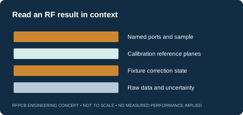
A VNA record should name its ports and measured quantities, together with the frequency sweep and setup conditions. Distinguish the uncorrected fixture-plus-device response from a result with fixture effects removed. Keysight’s de-embedding guidance explains why a characterized fixture model and intended reference plane are central to that distinction.
Request raw data and the configuration needed to understand any correction. If two reports disagree, first compare port mapping, reference impedance, connector inclusion and correction state before concluding that the boards differ. Do not assume a general PCB capability list includes this laboratory work. Confirm the measurement provider, fixture responsibilities and deliverable format in the RFQ.
Use microsections as local construction evidence
A microsection can reveal dimensions and structural details at a chosen cut, but its interpretation depends on where and how that sample was taken. Request a location reference, image scale, feature labels and the criteria used for the reported measurements.
Decide which features justify destructive examination before the order is prepared. An impedance coupon section, a plated hole and a castellation interface serve different questions. The sample plan should describe how that local evidence is used in the broader acceptance process. Avoid wording that turns one image into a claim that every hidden feature on every board was inspected.
Explore tolerance and expanded uncertainty as separate intervals
The tool accepts target impedance, tolerance percentage, measured impedance and expanded uncertainty in ohms. It calculates the allowed range as target multiplied by one minus or plus tolerance divided by one hundred. The measured interval is the entered result minus or plus the entered expanded uncertainty. The uncertainty is an input, not something inferred from the tolerance.
An interval entirely within the allowed range is labeled inside; a disjoint interval is outside; an interval crossing a boundary is overlap. Equality at a limit counts as inside when the entire interval remains contained. This is an exploratory guard-band illustration, not a contractual decision rule or a probability calculation. Obtain uncertainty and its coverage information from the responsible measurement provider.
Work through a clearly labeled illustrative example
Illustrative example, not a factory report. Suppose the target is 50 ohms with a tolerance of 10%. The allowed range is 45 to 55 ohms. An entered result of 54 ohms and expanded uncertainty of 2 ohms gives a measured interval from 52 to 56 ohms, so the calculator reports overlap.
The nominal result lies within the tolerance, while the illustrated interval extends beyond it. That observation does not itself reject a board or authorize shipment. A result of 50 ohms with the same uncertainty illustrates inside; 58 ohms with the same uncertainty illustrates outside. None of these numbers represents an RFPCB measurement, capability promise or recommended uncertainty budget.
Agree the decision and retain a reviewable record
Ask the measurement provider to state the uncertainty basis and coverage factor where uncertainty is reported. Keysight’s official help distinguishes uncertainty display settings and characterized contributions; a convenient software setting is not a substitute for the measurement plan. Define the decision rule separately and record who may authorize an exception.
Use the DFM checklist to attach the required evidence to the manufacturing request, and include its cost in the RF PCB cost plan. RFPCB’s shared-factory overview lists electrical test, TDR and microsection; the actual order still needs an agreed scope. Archive reports with the data revision, raw files and any disposition so repeat orders remain comparable.
Prepare a reviewable engineering request
Check only the requirements you have actually documented. This list records readiness; it does not inspect your files or certify a design. Missing information is useful: identify it explicitly so the engineering review can resolve it before a production release.
These inputs are processed in your browser and are not submitted by this tool. The downloaded summary is a plain-text planning record. Use the secure quote form to send files; request an NDA first if your project requires one.
Manufacturing context
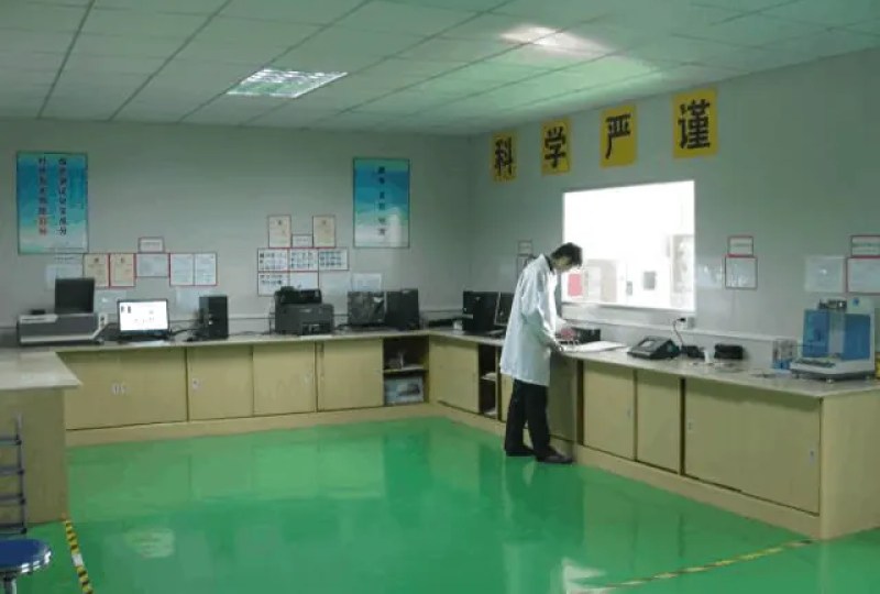
RFPCB and PCBSync share the manufacturing facility shown below. These process photographs illustrate the production environment; they are not evidence that a particular board, material grade or RF performance has been qualified. Request the documentation and inspection scope applicable to your project.


RF PCB test report FAQs
Does the interval calculator decide whether a board passes?
No. It shows a geometric relationship between an entered measurement interval and a tolerance range. Acceptance follows the separately agreed specification, uncertainty treatment and decision rule.
Is expanded uncertainty the same as tolerance?
No. Tolerance is the allowed requirement range. Expanded uncertainty describes uncertainty associated with a measurement under a stated evaluation and coverage basis; the tool does not calculate that budget.
Must every RF PCB order include VNA measurements?
No. Select testing from the design risks and purchased scope. If RF transmission or reflection data is required, agree the test article, provider, setup and deliverables explicitly.
Can these example results be used as a supplier report?
No. The examples demonstrate interval arithmetic only and are clearly labeled illustrative. A supplier report requires actual sample identity, methods, results and authorized review.
Continue your engineering review
Request evidence tied to your board and acceptance criteria
Send the fabrication revision, required methods, sample coverage and acceptance notes. Identify RF reference planes and any uncertainty or raw-data requirements before the inspection scope is quoted.
Sources and engineering scope
- Keysight: fixture characterization and measurement reference planes
- Keysight official help: real-time S-parameter measurement uncertainty
- PCBSync: shared-factory electrical test, TDR and microsection overview
Manufacturer values apply to the identified grade, test method and construction. Engineering examples on this page are illustrative; they are not measured product results, inventory statements or certification claims. Manufacturer and product names belong to their respective owners. Keep the applicable datasheet revision with your approved manufacturing package.
Ready for a quotation?
Send your requirements for a material, stackup and manufacturing review. Price and schedule are confirmed for your project.