
Thermally enhanced PTFE · TC350 and TC600
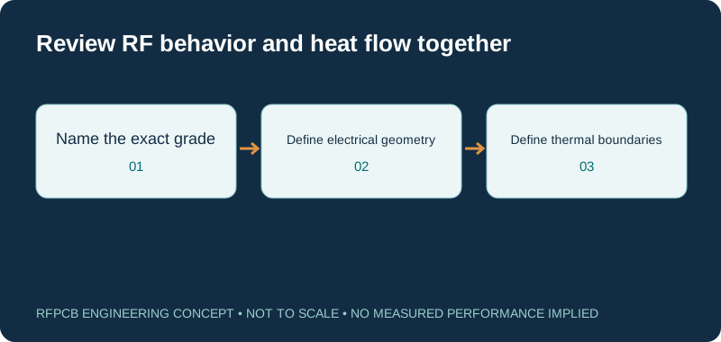
Rogers TC350 PCB and TC600 PCB requests combine RF geometry with a defined heat path. These are different PTFE-composite grades, and neither should be abbreviated to TC350 Plus. Review the named material, its test conditions and the completed board construction before choosing an electrical or thermal model.
TC350 and TC600 require separate models: their datasheets give nominal 10 GHz dielectric constants of 3.50 and 6.15. The retrieved TC350 sheet lists thermal conductivity 0.72 W/(m·K) under ASTM D5470; TC600 lists directional values under ASTM E1461. A thermal-material number does not specify a board temperature, power rating or approved manufacturing process.
TC350 versus TC600: keep grade and method attached
| Reference | TC350 | TC600 |
|---|---|---|
| Material class | Ceramic-filled, reinforced PTFE composite | Ceramic-filled, woven-glass PTFE composite |
| Nominal Dk at 10 GHz | 3.50; IPC TM-650 2.5.5.5 | 6.15; IPC TM-650 2.5.5.5 |
| Typical Df at 10 GHz | 0.0020; same electrical method | 0.0020; same electrical method |
| Thermal conductivity reference | 0.72 W/(m·K); ASTM D5470 | Z: 1.1; X/Y: 1.4 W/(m·K); ASTM E1461 |
| Retrieved document revision | 1683 111225; PUB#92-196 | 1611 080922; PUB#92-213 |
| Interpretation | Use the requested construction and applicable document | Different method and direction prevent a simple thermal ranking |
| Related name | TC350 Plus has its own material documentation | TC600 is not a higher-numbered TC350 Plus option |
Guided wavelength and size explorer
λg = c / (f × √εeff), with c = 299.792458 mm·GHz. Use the effective value of your actual geometry. Quarter wavelength excludes fringing, loading, dispersion, coupling and end corrections. It is not production-ready artwork.
Choose between complete constructions, not suffixes
The material list should spell out TC350 or TC600 at every point where purchasing or manufacturing uses it. A short reference such as “TC material” is insufficient when the dielectric models differ substantially. The TC350 datasheet and TC600 datasheet are the sources of the reference table. Keep the document revision with the approved stackup.
If the project actually specifies TC350 Plus, continue to the TC350 Plus manufacturing guide. Do not transfer its thermal conductivity or design-Dk entries into a TC350 request. An apparently small naming shortcut can affect both the simulation assumptions and the material ordered for a qualification build.
Separate dielectric data from electrical dimensions
A higher nominal material Dk can make a different electrical geometry worth investigating, but it does not prescribe a trace width or resonator length by itself. The signal structure, reference spacing and surrounding fields still determine the effective behavior. Rogers' Dk methods discussion explains why the value and test method need to stay connected.
Use the wavelength explorer with effective permittivity from the intended geometry. At 5 GHz and an illustrative effective value of 4.0, the simplified guided wavelength is about 29.98 mm and its quarter wavelength is about 7.49 mm. These are hypothetical inputs, not a TC600 layout recommendation. Fringing, coupling, discontinuities and dispersion require the appropriate circuit or electromagnetic model before artwork is released.
Define a thermal path before comparing conductivity
Thermal conductivity is a property used inside a heat-transfer model. The required temperature result also depends on the dissipated power, geometry, attachment and cooling boundary. The TC350 and TC600 reference values in the table use different methods; TC600 additionally distinguishes directions. Do not calculate a promised temperature reduction by dividing those entries.
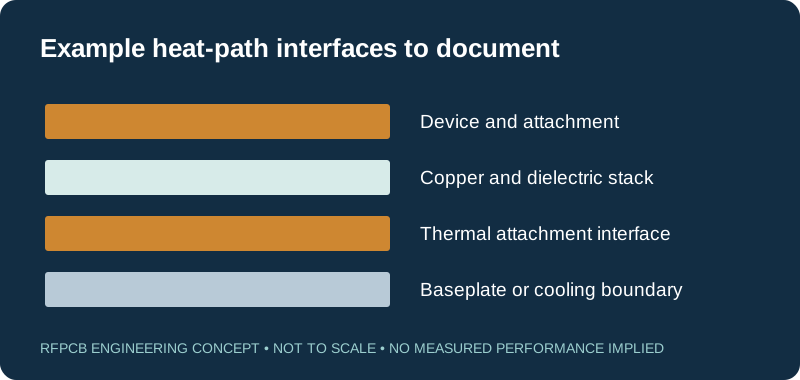
Draw the intended path from the device through its attachment, copper, dielectric and any baseplate interface. Identify parallel paths such as plated features when they are part of the design. State the expected ambient or mounting temperature and duty conditions. Rogers' thermal-management article provides context for considering material and circuit geometry together. Your qualification must use the assembly and boundary conditions that actually govern the product.
Do not confuse RF output power with board heating
An amplifier's RF output rating is not automatically the heat deposited into the PCB. Prepare a power-dissipation estimate for the device and relevant passive structures under the intended operating modes. Include the assumptions behind efficiency or loss figures and identify transient conditions that need separate review. This gives the thermal model a defined input instead of a marketing power number.
Set electrical and temperature acceptance criteria separately. A board can meet a small-signal RF target while failing a required thermal operating condition, or stay cool while its matching network misses the intended response. Select representative test conditions that exercise both requirements. Record input drive, supply, duty cycle and mounting state with the result so a later comparison does not attribute a changed operating condition to the laminate.
Review plated holes and bonding as PTFE construction work
A TC350 or TC600 core does not define the bonding material or the plated-hole process for a multilayer board. Request a construction-specific review of the layers traversed by each important interconnect. Identify finished-hole requirements and any thermal or signal role assigned to those holes. Do not convert a general material description into a blanket claim that every hole schedule is qualified.
The linked TC fabrication guide currently names TC350 and TC350 Plus in its material description despite its broader filename. Confirm the applicable guidance for TC600 separately. Ask the fabricator to document the relevant handling, bonding and hole-preparation approach. Published processing guidance supports the review; it is not an approval of the proposed finished board.
Allocate RF loss over a defined path
The two 10 GHz Df entries are not predictions of equal insertion loss in two finished designs. Different trace dimensions, copper conditions, transitions and matching structures can change the measured result. Define whether the requirement covers a uniform line, a passive network or the whole connector-to-connector path. Compare data at the operating band and at consistent boundaries.
If a smaller structure is the reason to consider TC600, include the resulting conductor geometry in the evaluation. If heating is the main concern, identify how distributed RF loss enters the thermal model. Keep measured and modeled quantities labeled. The RF loss guide helps organize the contributions, while a representative coupon can resolve a specific interconnect uncertainty without claiming to qualify an entire amplifier.
Design the prototype to reveal the limiting factor
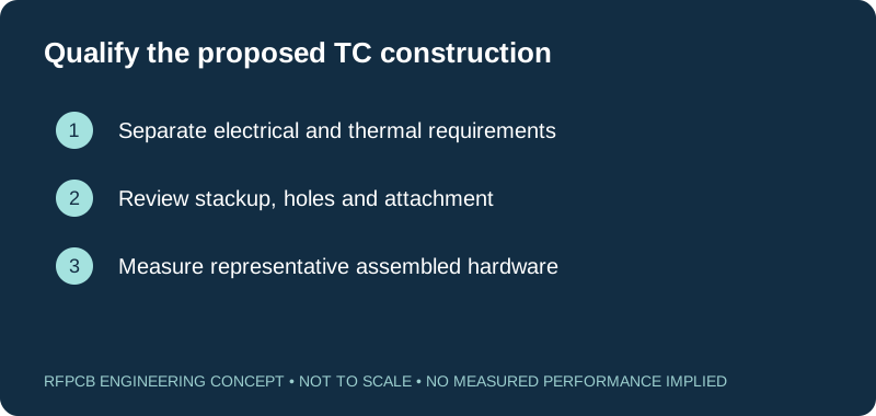
Choose a prototype that includes the uncertain electrical and thermal interfaces. A thermal coupon may answer a controlled heat-flow question, while a populated circuit is needed to evaluate device operation and the actual mounting arrangement. State the sample purpose so its results are not generalized beyond the experiment. Include measurement locations and how attachment will be reproduced.
Plan a baseline and a changed construction when comparing grades. If more than the laminate changes, identify those changes before analyzing the data. Preserve assembly records, measured geometry and test conditions. When the result misses a target, use the next test to distinguish possible causes rather than immediately selecting a new material. A structured experiment can reveal that a connector, attachment interface or unmodeled operating state deserves attention first.
Resolve sourcing and quotation assumptions before release
Ask for current confirmation of the grade, core thickness, copper and quantity required. A datasheet configuration is not an inventory commitment, and another project's completed build does not establish the scope of your order. If a different construction is proposed, request the changed electrical, thermal and inspection assumptions in writing.
Compare delivered quotations with the same manufacturing files, acceptance criteria and delivery basis. Keep prototype qualification and any assembly work visible as separate costs. Give the team a defined substitution approval path so schedule pressure does not produce an undocumented material change. Use the checklist below to identify missing requirements, then attach the approved construction and test plan to the production package. The result should be a traceable board proposal, not an unqualified promise based on thermal conductivity alone.
Prepare a reviewable engineering request
Check only the requirements you have actually documented. This list records readiness; it does not inspect your files or certify a design. Missing information is useful: identify it explicitly so the engineering review can resolve it before a production release.
These inputs are processed in your browser and are not submitted by this tool. The downloaded summary is a plain-text planning record. Use the secure quote form to send files; request an NDA first if your project requires one.
Manufacturing context
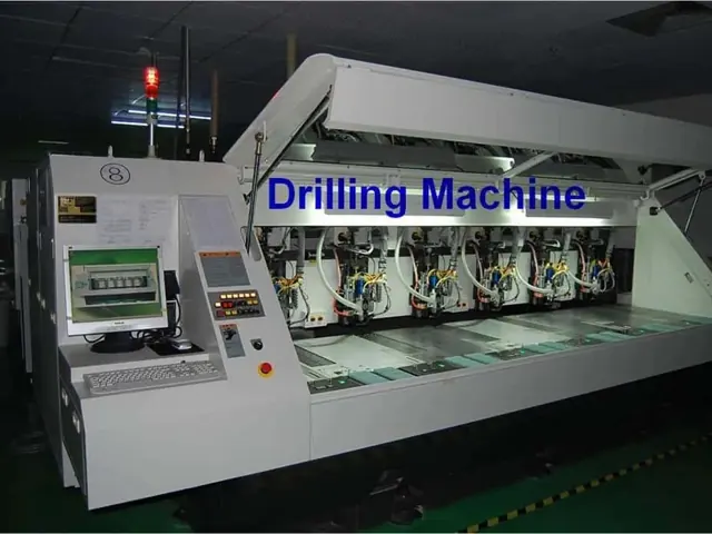
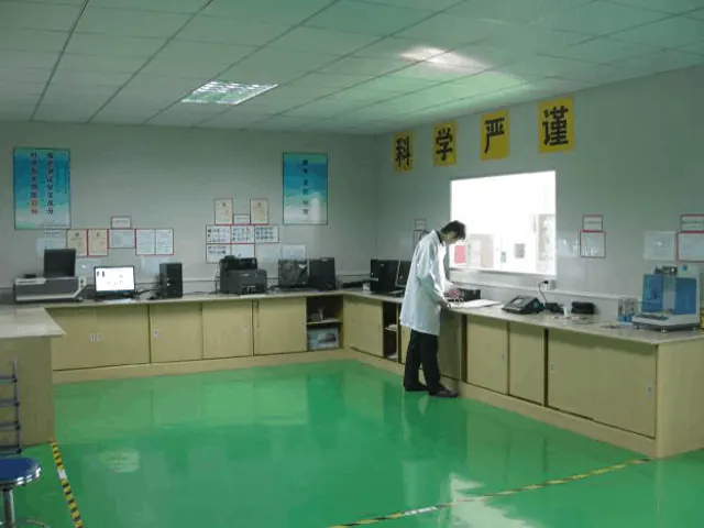
RFPCB and PCBSync share the manufacturing facility shown below. These process photographs illustrate the production environment; they are not evidence that a particular board, material grade or RF performance has been qualified. Request the documentation and inspection scope applicable to your project.

TC350 / TC600 PCB questions
Is TC350 the same as TC350 Plus?
No. Keep the complete product designation in the drawing and request. The Plus grade has separate documentation and must not supply unqualified values for a TC350 construction.
Why is TC350 thermal conductivity listed as 0.72 here?
That is the value in the retrieved Rogers TC350 datasheet, revision 1683 111225, using ASTM D5470. Do not replace it with an older number or a TC350 Plus value without identifying the applicable source and method.
Does TC600 guarantee a smaller or cooler amplifier?
No. Its material properties support evaluating a different construction. Circuit dimensions, loss, device dissipation, mounting and cooling determine the finished result and need separate models and measurements.
Can RFPCB confirm a layer count or power rating from the material name?
Those requirements need a project-specific review. Supply the stackup, interconnects, heat path and acceptance scope so feasibility and the proposed evidence can be discussed for the actual board.
Continue your engineering review
Request a TC350 or TC600 construction review
Send the exact grade, RF requirements, power-dissipation assumptions, stackup and mounting arrangement. Include requested test evidence so the manufacturing and sourcing proposal can be assessed against your design.
Sources and engineering scope
- Rogers TC350 datasheet, retrieved revision 1683 111225, publication 92-196
- Rogers TC600 datasheet, revision 1611 080922, publication 92-213
- Rogers TC fabrication guide: retrieved text names TC350 and TC350 Plus; confirm applicability for TC600
- Rogers: Optimizing Thermal Management for Wireless Communication Systems
- Rogers: Managing PCB Materials Dielectric Constant (Dk), measurement and design context
Manufacturer values apply to the identified grade, test method and construction. Engineering examples on this page are illustrative; they are not measured product results, inventory statements or certification claims. Manufacturer and product names belong to their respective owners. Keep the applicable datasheet revision with your approved manufacturing package.
Ready for a quotation?
Send your requirements for a material, stackup and manufacturing review. Price and schedule are confirmed for your project.