
Thermally enhanced epoxy · Construction and evidence
Rogers 92ML PCB inquiries concern a thermally enhanced epoxy laminate and prepreg system. Specify where heat must flow and what electrical function each layer performs. This guide uses a manufacturer-authored 2019 datasheet available through a distributor mirror; current document applicability and the requested material supply must be confirmed for the project.
Evaluate 92ML as a complete thermal and electrical construction. Its historical property table reports directional thermal conductivity and electrical values at 1 MHz. Those entries do not make it interchangeable with a microwave PTFE laminate or establish GHz loss. Separate the heat-path requirement from RF material selection, then review the stackup, processing and measurement plan.
92ML historical references: direction and test method matter
| Reference | 2019 manufacturer property table | Project implication |
|---|---|---|
| Document | Issued 1418 042619; publication 92-185 | Historical distributor-hosted copy; confirm applicable specification |
| Material system | Thermally enhanced epoxy laminate and prepreg | Keep core and bonding construction explicit |
| Conductivity at 23°C | X/Y: 2.3; Z: 1.7 W/(m·K), ASTM E1461 | Use the direction relevant to the modeled heat path |
| Conductivity by another method | Z: 1.6 W/(m·K), 50°C, ASTM D5470-12 | Do not combine methods as interchangeable limits |
| Electrical reference | Dk 5.28; Df 0.011 at 1 MHz, IPC TM-650 2.5.5.3 | These are not 10 GHz characterization results |
| Data interpretation | Cover-page thermal claims differ from the property table | Request clarification; do not mix numbers from different sections |
| Supply and qualification | No current inventory or completed-board approval established | Confirm requested construction and agreed tests before release |
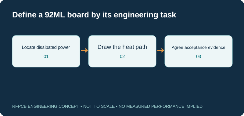
Define the role of 92ML in the product
The material name should identify a particular job in the stack: carrying a circuit, bonding layers or contributing to a heat-transfer path. State that job before comparing it with a dedicated RF laminate. A power-control board and an RF feed board may need different electrical evidence even if both operate near a high-power component. The manufacturer's name does not make all of its material families interchangeable.
Draw the relevant layer functions and mark heat sources. Identify which regions carry sensitive signals and which provide power distribution or mechanical attachment. If a separate RF board attaches to the thermal structure, include that interface in the review. This keeps the material decision connected to the physical product rather than treating a single conductivity figure as a complete design specification.
Use a versioned property table, not an isolated sales figure
The 92ML manufacturer datasheet mirrored by CCI Eurolam is issued 1418 042619. Its property table contains the directional and test-specific entries shown above. The cover text contains different thermal figures. This guide uses the table as a historical reference and flags the inconsistency instead of choosing whichever number makes the material appear most attractive.
Request the applicable manufacturer specification before using those values in an order or validated model. Record whether an entry is typical, a limit or a project measurement. A datasheet copy can establish the provenance of a value without establishing current supply. Do not infer that a product is available, unavailable or discontinued from the date of a mirrored document. Resolve those questions separately for the requested construction.
Keep 1 MHz properties out of an unsupported GHz model
The table's electrical test frequency is part of the property definition. It cannot be silently relabeled as a microwave result. If a critical RF path interacts with 92ML, request suitable frequency-dependent material information or a justified characterization plan. State which quantities need modeling: impedance, propagation, attenuation or coupling. A useful requirement is more specific than asking whether the material is “good for RF.”
If the RF circuitry uses a separate known dielectric, review the reference conductor and transitions that bound that structure. Confirm where fields or interconnects enter the thermal-material region. Compare the complete arrangement rather than assuming the supporting layers are electrically invisible. The material-selection guide helps turn each layer's function into the data and acceptance evidence it requires.
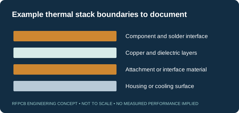
Describe dissipated power and thermal boundaries
Prepare a power map for the operating states that drive the design. Distinguish continuous dissipation from short-duration conditions and document the input assumptions. Include the ambient or cooling-surface conditions used in the calculation. Without those boundaries, a quoted temperature rise is difficult to interpret or reproduce, regardless of the laminate chosen.
Identify interfaces between the device, solder, copper, dielectric, attachment material and cooling structure. Decide which paths run through the thickness and which spread laterally. Rogers' thermal-management discussion supports considering circuit construction alongside material properties. A system model and representative measurements should determine the temperature result; material conductivity alone cannot establish a universal wattage capability or component junction temperature.
Build the layer stack around both copper and resin
A 92ML multilayer proposal needs more than total thickness and layer count. Identify core and prepreg roles, finished dielectric spacing, copper distribution and the interfaces that transfer heat. Mark any thickness that is constrained by component assembly, electrical behavior or attachment. Ask how the proposed stack will meet those constraints after lamination.
Treat a change in copper or bonding construction as a change to the model when it affects the critical path. Do not assume that a heavier copper selection solves every heat-transfer bottleneck. Review clearances, filling around features and final geometry with the fabricator. The hybrid-stackup guide is useful if the proposal combines different material functions. Keep each constituent material identifiable in the approved construction and purchasing record.
Review fabrication guidance without turning it into a recipe
A manufacturer-authored 2016 92ML fabrication guide preserved in an archive discusses storage, multilayer processing and material tracking. It is historical guidance, not proof that a particular production process is currently qualified. Ask the fabricator to confirm the applicable handling, bonding and hole-preparation requirements for the proposed material and stack.
Provide the hole schedule, copper features, outline and assembly conditions needed for that review. Identify processing or rework exposures that the finished board must tolerate. Request the relevant inspection evidence where a feature is important to acceptance. Do not copy a bake cycle or processing limit from an older document into a production instruction without resolving applicability to the current material, equipment and construction.
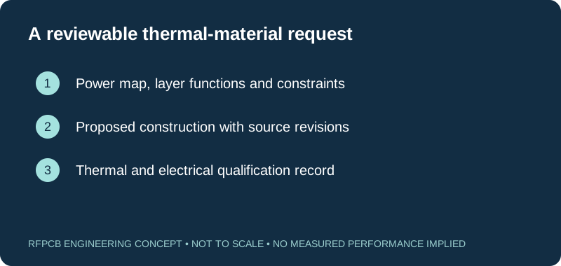
Distinguish the material family from a metal-backed assembly
A laminate and prepreg system does not by itself specify a finished metal-backed PCB, its attachment or an insulated-metal-substrate product. If the drawing uses a related product name or a metal base, identify it explicitly. The stackup should show which layer provides insulation, how it is bonded and how the completed structure interfaces with the housing or heat sink.
Keep electrical isolation requirements separate from thermal goals. Provide the required test method and acceptance scope for the finished assembly rather than treating a datasheet electrical-strength entry as an automatic system rating. Where product-specific safety or reliability requirements apply, supply the applicable design requirements and required records. A quotation can then address the actual construction instead of assuming that one thermal-material label resolves every interface.
Measure the assembled heat path and record the operating state
Choose temperature measurement locations and methods that answer the design question. Record power, duty cycle, mounting, airflow and stabilization criteria with the results. A surface reading at one location is not automatically the component junction temperature or the worst-case temperature of the assembly. State which result is directly measured and which is inferred by a model.
For a material comparison, keep the relevant construction and operating conditions consistent, or identify every difference that affects interpretation. Include electrical measurements when thermal changes can alter the required circuit response. Preserve the sample identity and assembly record so a second build can reproduce the comparison. The test-report guide helps structure these records without turning an isolated coupon result into approval of the whole product.
Use the checklist to prepare a focused engineering inquiry
The interactive checklist records information you have prepared; it does not inspect a thermal model or certify a construction. Use its notes area to identify missing current material documents, uncertain power estimates and interfaces needing review. Attach the stackup, manufacturing files, assembly information and requested evidence when submitting the actual project.
Ask for a proposed construction and a quotation with clear assumptions about quantity, sourcing, inspection and test scope. If 92ML cannot be confirmed for the request, evaluate alternatives against the same thermal and electrical requirements. Keep the qualification work visible in the decision. The approved output should identify the material, geometry, process scope and evidence supporting the next build, with current supply confirmed for that order rather than implied by this reference page.
Prepare a reviewable engineering request
Check only the requirements you have actually documented. This list records readiness; it does not inspect your files or certify a design. Missing information is useful: identify it explicitly so the engineering review can resolve it before a production release.
These inputs are processed in your browser and are not submitted by this tool. The downloaded summary is a plain-text planning record. Use the secure quote form to send files; request an NDA first if your project requires one.
Manufacturing context
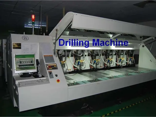
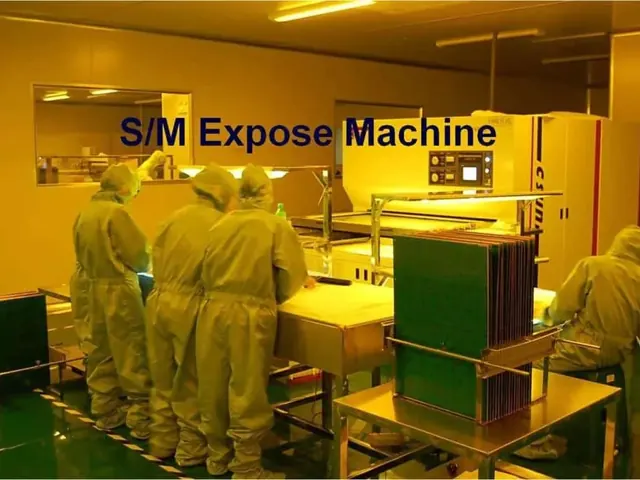
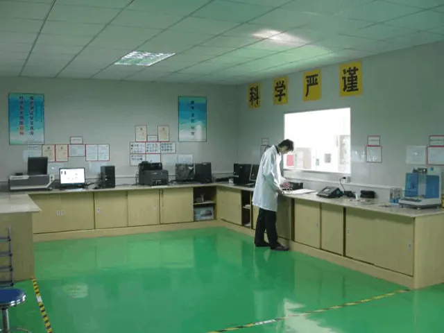
RFPCB and PCBSync share the manufacturing facility shown below. These process photographs illustrate the production environment; they are not evidence that a particular board, material grade or RF performance has been qualified. Request the documentation and inspection scope applicable to your project.
92ML PCB questions
Is 92ML a PTFE microwave laminate?
The referenced manufacturer document describes an epoxy laminate and prepreg system. Select it for a defined construction and verify any RF interaction separately; do not transfer the properties of TC350, TC600 or other PTFE grades.
Can its 1 MHz Dk and Df be used as 10 GHz data?
No. Preserve the published frequency and method. A critical microwave path needs appropriate material modeling or characterization at its operating band.
Why are several thermal-conductivity values shown?
The historical property table distinguishes direction, temperature and method. Its cover text also differs from the table. Keep each context intact and request the applicable manufacturer specification instead of combining the numbers into one claimed limit.
Does this page confirm 92ML stock or a maximum board power?
No. Current supply is project-specific, and board temperature depends on power distribution, construction, interfaces and cooling. Provide those requirements for a reviewed proposal and qualification plan.
Continue your engineering review
Request a 92ML thermal-construction review
Provide the layer stack, power map, mounting conditions and electrical requirements. Include the material records you have and the documentation, sourcing or test questions that must be resolved before the next build.
Sources and engineering scope
- Rogers 92ML manufacturer datasheet, issued 1418 042619, historical CCI Eurolam mirror
- Rogers 92ML fabrication guidelines, issued 1231 041816, historical manufacturer-authored archive copy
- Rogers: Optimizing Thermal Management for Wireless Communication Systems
- Rogers: Managing PCB Materials Dielectric Constant (Dk), measurement and design context
Manufacturer values apply to the identified grade, test method and construction. Engineering examples on this page are illustrative; they are not measured product results, inventory statements or certification claims. Manufacturer and product names belong to their respective owners. Keep the applicable datasheet revision with your approved manufacturing package.
Ready for a quotation?
Send your requirements for a material, stackup and manufacturing review. Price and schedule are confirmed for your project.