
Thermally enhanced PTFE laminate · Manufacturing review
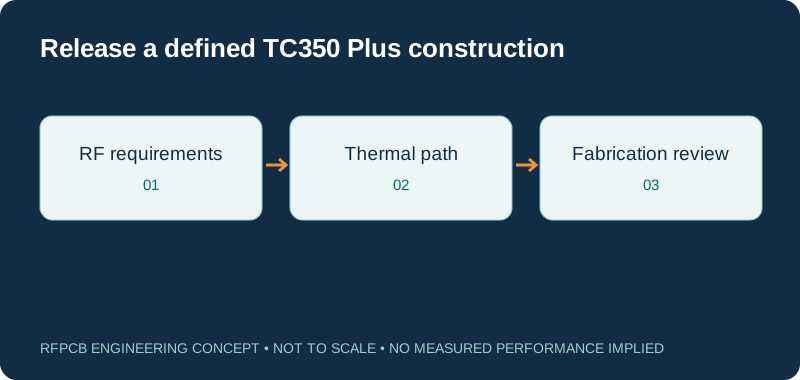
Rogers TC350 Plus PCB manufacturing starts with an agreed RF and thermal construction. TC350 Plus is a ceramic-filled, woven-glass-reinforced PTFE laminate. Submit the exact core, copper, layer arrangement and acceptance scope so the proposed board can be reviewed against your power, loss and mechanical requirements.
Specify TC350 Plus by its complete grade name and proposed construction. Rogers publishes process Dk 3.50 ± 0.05, design Dk 3.62, typical Df 0.0017 at 10 GHz, and thermal conductivity 1.24 W/(m·K). These references support material selection; the fabrication proposal must separately establish stackup, hole processing, sourcing and finished-board acceptance.
TC350 Plus references and their manufacturing implications
| Reference | Published context | Project decision |
|---|---|---|
| Material system | PTFE with ceramic filler and woven glass | Review PTFE processing and the complete bonding construction |
| Process Dk | 3.50 ± 0.05 on the Rogers product page; datasheet nominal 3.50 at 10 GHz | Keep the material specification separate from impedance acceptance |
| Design Dk | 3.62; microstrip differential phase length, 10 GHz | Choose the appropriate model for the RF geometry |
| Typical Df | 0.0017 at 10 GHz; IPC TM-650 2.5.5.5 | Allocate finished-route loss using suitable modeling or measurements |
| Thermal conductivity | 1.24 W/(m·K), Z direction; ASTM D5470 | Define the complete heat path and mounting boundary conditions |
| Published core options | Standard nominal 10, 20, 30 and 60 mil cores | Confirm the requested thickness, foil and supply with the quotation |
| Production scope | Construction and inspection require project review | State quantity, revision, test articles and acceptance criteria |
RF route loss budget worksheet
Total = length × entered attenuation + total launch/transition allocation + other passive loss. Frequency labels the scenario; it does not synthesize an attenuation model. Use comparable data at that frequency and avoid counting the same feature twice. Adding scalar dB terms is a matched or weak-reflection planning approximation; use cascaded S-parameters for mismatched structures. Default values are illustrative.
Define the TC350 Plus order before quoting
Put “Rogers TC350 Plus” on the fabrication drawing and identify the dielectric thickness, cladding and finished copper requirements. Keep the Plus suffix in the bill of materials, purchasing request and supplier response. A request for “TC350” or “Rogers 3.5 Dk” leaves ambiguity about which material has been selected. If an alternative is permitted, name it separately and explain the approval needed before use.
Attach the board outline, layer count, fabrication data and hole schedule to the same revision. State whether the submission is an early feasibility study, a prototype release or a repeat order. A reviewer can then distinguish flexible design choices from dimensions already fixed by an enclosure, connector or qualified assembly. Use the TC350 Plus laminate properties explainer when the material terminology needs clarification before the drawing is released.
Match the stackup to the RF model
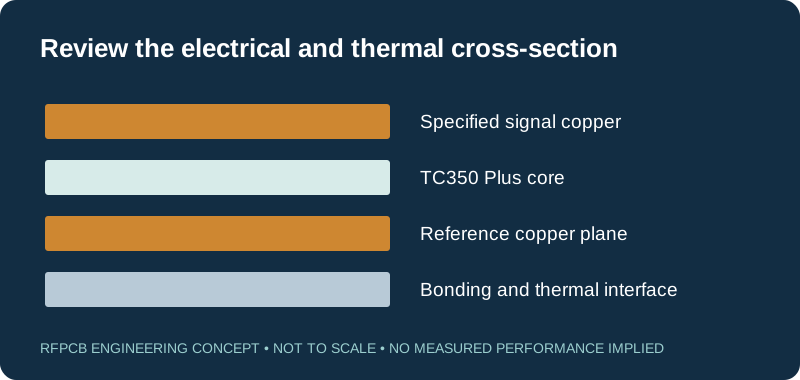
For each sensitive transmission line, show its signal layer, reference conductor, dielectric spacing and any nearby solder mask or bonding material. Identify whether the structure is microstrip, grounded coplanar waveguide or an embedded line. The laminate name alone does not define its impedance. Trace width, conductor thickness, gaps and the surrounding dielectric regions all belong in the reviewed construction.
The TC350 Plus datasheet separates process and design dielectric constants. Its process Dk and Df conditions are 23°C, 50% relative humidity and 10 GHz. Do not present the product-page process tolerance as a finished-board impedance tolerance. Request an agreed calculation basis and define how the completed board will be checked. The controlled-impedance guide helps connect the intended geometry, coupon and report to a measurable requirement.
Provide a usable thermal requirement
Specify dissipated power where possible, not only amplifier output power. Include duty cycle, ambient or enclosure conditions, cooling arrangement and the maximum temperatures relevant to the assembly. Mark component thermal pads, copper areas, mounting surfaces and any proposed vias or metal features. This turns a general request for a thermally enhanced material into a heat-flow problem that engineering can actually review.
Thermal conductivity describes the dielectric; it does not establish a board temperature or an allowable wattage. The heat path may include copper spreading, a bonding film, a mounting interface and a heatsink. Each can change the result. Rogers discusses these tradeoffs in its thermal-management article. Agree the proposed model and the conditions of any prototype temperature measurement before treating a construction as approved for sustained power.
Review plated holes as part of the material system
The Rogers TC-series fabrication guide calls for treating drilled PTFE hole walls before depositing the conductive seed layer. It discusses sodium and plasma activation, while distinguishing that treatment from desmear required by a multilayer adhesive. A note saying “standard desmear” therefore does not completely describe the preparation of a mixed-material hole.
Provide finished-hole sizes, pad diameters, board thickness and the layers each hole crosses. Identify grounding vias and component connections whose function makes voids or interrupted plating especially consequential. Ask the fabricator to review preparation and inspection for that construction. Select cross-section and reliability evidence according to the project requirement, rather than assuming that a laminate property alone proves plated-hole performance. Small-hole feasibility, tool life and registration allowances need confirmation against the actual manufacturing proposal.
Resolve bonding and dimensional choices together
A TC350 Plus core may be only one part of a multilayer board. Name the proposed bonding layers, their pressed thicknesses and the electrical regions they create. If the RF layer shares a construction with control or power circuitry, mark the features that must remain fixed during optimization. Review a hybrid stackup as a complete candidate, including its thermal and assembly consequences.
Rogers ties the press cycle to the selected adhesive system in the TC-series guide. That is a reason to obtain a construction-specific proposal, not to prescribe one universal cycle from a web page. Request that engineering identify any process-driven changes to copper distribution, layer registration or mechanical dimensions. For coupled lines, filters and connector footprints, clearly state which dimensions require approval before adjustment. Keep the final stackup with the fabrication files so subsequent orders use the same reviewed definition.
Specify copper, finish and exposed RF surfaces
Record the copper foil designation and distinguish starting cladding from finished plated copper. Also identify the final surface treatment and any solder-mask exclusions around critical structures. These details make the electrical cross-section reproducible and help the reviewer assess changes near connectors, resonators and component pads. A generic copper weight without the rest of the geometry cannot fully describe the signal path.
Rogers explains that copper roughness affects high-frequency conductor loss and phase behavior in its circuit-material application notes. Compare candidate builds with a consistent foil and finish basis, or document the difference explicitly. If a different surface treatment is proposed for assembly needs, revisit the sensitive RF structures. Request evidence for the chosen construction instead of assuming that low dielectric loss automatically makes every copper and finish combination equivalent.
Use the loss worksheet for a defined path
Enter attenuation for the uniform route at the operating frequency, then add separate allowances for launches, transitions and other passive elements. The worksheet multiplies route length by the entered attenuation and compares the resulting total with your allowed path loss. Frequency labels the scenario; the tool does not calculate attenuation from TC350 Plus Df or predict how loss changes across a band.
For example, an illustrative 50 mm route at 0.01 dB/mm contributes 0.50 dB. Adding 0.30 dB for launches and 0.20 dB for other passive loss gives 1.00 dB, leaving 0.50 dB against a 1.50 dB allowance. None of those inputs are measured TC350 Plus performance. Avoid counting a launch both within measured route attenuation and again as a separate term. Use cascaded S-parameters when reflections make scalar loss addition inadequate, and retain the same measurement boundaries when comparing prototypes.
Agree inspection and electrical evidence before fabrication
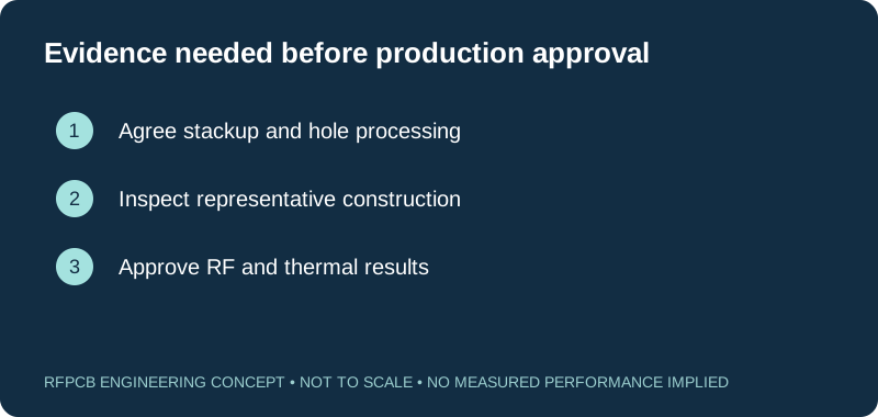
Separate material traceability, dimensional inspection, continuity testing and RF characterization in the purchase requirement. They answer different questions. A connectivity pass establishes neither an insertion-loss limit nor a phase-balance limit. A controlled-impedance coupon also needs a construction and measurement method that represent the intended requirement. Identify the critical line geometry, relevant layers and acceptable reporting scope before deciding which evidence to order.
For measured RF deliverables, specify frequency range, reference planes, connector or fixture treatment, sample quantity and numerical acceptance limits. State whether thermal exposure or assembly occurs before testing. The RF test report guide explains the information needed to interpret a report. Retain raw or agreed processed data with the board revision and stackup. This allows later investigations to separate a measurement change from a physical change in the circuit.
Compare quotations on the delivered construction
Request quantities and delivery requirements alongside the technical package. Ask the proposal to identify material allocation, fabrication, additional coupons, inspection and any separately priced measurements. Confirm the requested thickness and copper configuration during sourcing review. A manufacturer listing is useful for describing possible material configurations, but it does not establish a fabricator's present inventory, minimum order or delivery date.
When cost reduction is necessary, show which constraints can be reconsidered: board outline, panel utilization, layer count, test scope or an unqualified material alternative. Compare the delivered scope consistently through the RF PCB cost worksheet. Include the time and expense of any qualification change. A lower bare-board figure may not reduce project cost if it requires new artwork, a revised fixture or another test campaign before the assembly can be released.
Keep the approved construction attached to repeat orders
Close the review with a dated stackup, the agreed material designation, approved fabrication notes and the required inspection records. Identify the person or team responsible for accepting deviations. Make substitutions visible on the engineering record rather than relying on a purchasing conversation that the next production reviewer may never see. A repeat order should refer to this approved package and its revision.
Reopen the relevant review if the foil, core thickness, bonding system, finish or sensitive layout changes. State what previous evidence still applies and what needs another check. For a new TC350 Plus project, submit the checklist and manufacturing files through the RFPCB quote form. The useful next step is a documented response that resolves construction, supply assumptions and acceptance scope, with open engineering items identified before they affect a production commitment.
Prepare a reviewable engineering request
Check only the requirements you have actually documented. This list records readiness; it does not inspect your files or certify a design. Missing information is useful: identify it explicitly so the engineering review can resolve it before a production release.
These inputs are processed in your browser and are not submitted by this tool. The downloaded summary is a plain-text planning record. Use the secure quote form to send files; request an NDA first if your project requires one.
Manufacturing context
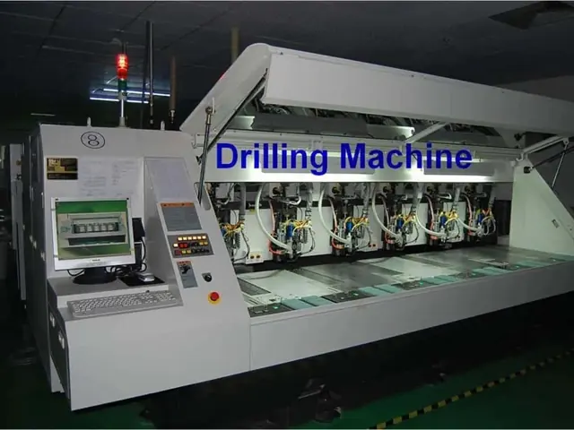
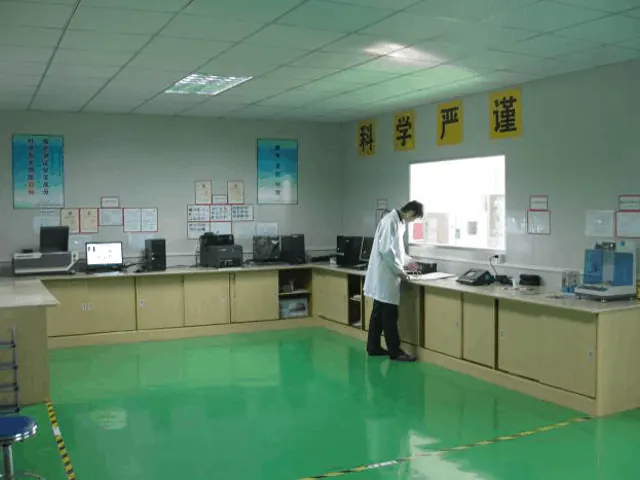
RFPCB and PCBSync share the manufacturing facility shown below. These process photographs illustrate the production environment; they are not evidence that a particular board, material grade or RF performance has been qualified. Request the documentation and inspection scope applicable to your project.

Rogers TC350 Plus PCB manufacturing questions
Is TC350 Plus a thermoset laminate?
No. Rogers identifies TC350 Plus as a PTFE-based composite containing ceramic filler and woven-glass reinforcement. A thermosetting bonding layer may appear in a proposed multilayer construction, but that does not change the identity of the TC350 Plus core.
Can the design Dk of 3.62 be used as effective permittivity?
Not automatically. Design Dk is a material-model reference obtained by the stated method. Effective permittivity belongs to the transmission structure and its surrounding fields. Use a model appropriate to the stackup, foil, geometry and operating band.
Does 1.24 W/(m·K) specify the PCB power rating?
No. Power handling also depends on conductor geometry, losses, heat spreading, mounting interfaces, cooling and operating duty. Supply those conditions for a thermal review and define prototype verification against the temperature limits of the actual assembly.
Are all listed TC350 Plus thicknesses ready to order?
Availability must be checked for the requested thickness, foil, quantity and manufacturing scope. The standard configurations in Rogers literature are material references. Request a project quotation that states the selected construction, sourcing assumptions and delivery basis.
Continue your engineering review
Request a TC350 Plus construction review
Send the fabrication revision, proposed stackup, RF band, thermal conditions and order quantities. Identify required measurements and any permitted alternatives so the response can address a defined board and acceptance scope.
Sources and engineering scope
- Rogers: TC350 Plus product overview and process/design Dk references
- Rogers: TC350 Plus laminate datasheet, composition, methods and typical properties
- Rogers: TC-series fabrication guidelines, including TC350 Plus
- Rogers: Optimizing Thermal Management for Wireless Communication Systems
- Rogers: High-Frequency Circuit Material App Notes, copper roughness and RF behavior
Manufacturer values apply to the identified grade, test method and construction. Engineering examples on this page are illustrative; they are not measured product results, inventory statements or certification claims. Manufacturer and product names belong to their respective owners. Keep the applicable datasheet revision with your approved manufacturing package.
Ready for a quotation?
Send your requirements for a material, stackup and manufacturing review. Price and schedule are confirmed for your project.