
Application engineering · Filters and duplexers
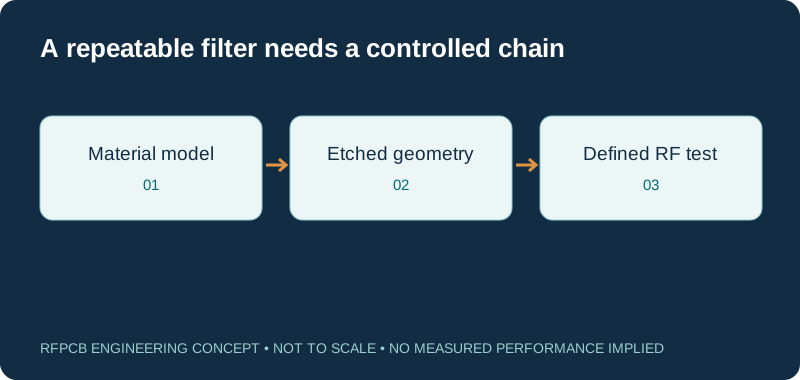
RF filter and duplexer PCB manufacturing needs a controlled relationship between material, geometry and measurement. Define the response you need, identify the features that control it, and agree the fabrication and acceptance plan before ordering.
A filter PCB may implement distributed filtering or carry packaged filter components; those are different manufacturing tasks. For a distributed circuit, dielectric construction, etched dimensions and coupling can directly affect the response. For an assembled module, transitions, placement, grounding and test fixtures also matter.
Translate RF requirements into manufacturing information
| RF requirement | Information to specify | Evidence to agree |
|---|---|---|
| Passband and insertion loss | Frequency range, limits and reference planes | Calibrated RF measurement on the agreed article |
| Center frequency and bandwidth | Material model, resonator dimensions and tolerances | Prototype correlation and controlled artwork |
| Stopband rejection / isolation | Sweep range, dynamic range and port terminations | Fixture-aware measurement method |
| Impedance and transitions | Stackup, controlled routes and launches | Geometry review; coupons where appropriate |
| Production repeatability | Material identity, dimensional controls and tuning policy | Traceability and agreed inspection records |
Resonance sensitivity explorer
f₂ = f₁ × (L₁/L₂) × √(εeff₁/εeff₂). Hold geometry and coupling assumptions consistent. These are effective permittivities from a transmission-line model, not automatically the published bulk or process Dk. The calculation illustrates sensitivity rather than synthesizing a filter.
Distinguish distributed filters from filter carrier boards
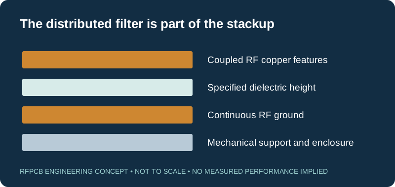
A distributed microstrip or stripline filter uses PCB geometry as part of the filtering network. Line widths, resonator lengths, coupling gaps and reference planes can directly influence the response. A carrier board for a packaged filter has another emphasis: launches, routing, grounding and assembly must preserve the component performance in the installed circuit.
Tell the fabricator which case applies and identify any combination of the two. A duplexer adds the need to define the relationship among ports and bands. The manufacturing drawing should make critical features visible instead of relying on a generic “RF board” description.
Select material against the actual response requirements
Begin with the operating bands, loss budget, size constraints and temperature conditions. The lowest published dielectric loss is not the only decision. Copper profile, geometry and mechanical stability can affect the final result. Compare named material grades using consistent methods and preserve the source of the electrical model.
The RO3003 versus RO4350B comparison is useful for a PTFE/thermoset discussion. The RO3006 and RO3010 guide addresses higher-Dk candidates where compact structures are being considered. None of these pages substitutes for a circuit-specific design review.
Build a tolerance budget for critical features
A resonant response can be sensitive to dielectric thickness, effective permittivity, line length and coupling geometry. Identify the dominant sensitivities with a suitable model, then translate them into dimensions and material requirements the manufacturing process can control. Uniformly tightening every drawing tolerance is rarely a clear specification.
The sensitivity tool above illustrates the first-order relationship among electrical length, effective permittivity and resonance. It does not include coupling or loading. Use it to understand the direction of a change, then analyze the complete structure before assigning production limits or predicting bandwidth.
Review etching, copper and surface finish together
The finished conductor cross-section can differ from an ideal rectangular trace in a model. Copper thickness, etch shape and finish can affect both geometry and losses. On coupled structures, a small change in gap may matter differently from a similar change on a noncritical support trace.
Specify which areas are RF-critical and discuss an appropriate inspection method. The surface-finish guide helps connect electrical, assembly and storage needs. Do not assume that a visually similar finish has the same structure or that every finish is interchangeable on a validated filter.
Keep the RF return path and enclosure in the model
Ground continuity, via placement and connection to the enclosure can influence unwanted modes and coupling. A layout with the correct nominal line impedance can still behave poorly around a plane break, launch or resonator boundary. Review the return path at the same time as the signal path.
If a lid, cavity, shield or metal carrier is part of the product, provide its geometry and attachment assumptions. The bare board measured on a bench may not represent the installed circuit. Mechanical changes should be included in the design revision and qualification discussion.
Define insertion loss, rejection and isolation tests precisely
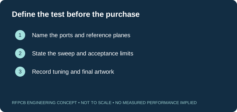
State the sweep range, port configuration, terminations and reference planes. Identify whether connectors, cables and transitions are included in the acceptance result. A fixture can introduce loss and resonances that obscure the behavior of the board, especially when the required rejection approaches the measurement system limits.
Agree calibration or de-embedding responsibilities before ordering special tests. A continuity test, an impedance coupon and a network-analyzer measurement are not interchangeable. Each answers a different question, and the quotation should identify which evidence is included rather than implying that every RF measurement is standard.
Establish a clear tuning policy
Some designs reserve features for controlled tuning during development. If tuning is expected, state who performs it, which features may change and how the final condition is recorded. Manual prototype adjustments can be useful, but they do not automatically create a repeatable production instruction.
After the response is accepted, update the artwork or document the approved tuning operation and inspection method. Preserve before-and-after measurements where useful. Repeating a prototype build from an untuned original file while expecting the tuned response is an avoidable source of confusion.
Separate bare-board, assembly and RF test scope
An RF filter project may require fabrication only, assembly from a BOM, or a fully tested module. Quote those scopes explicitly. Assembly information includes component variants, orientation, placement data, soldering constraints and any shield or connector installation requirements.
Use the RF PCB assembly page when requesting a populated product. If you will assemble and test internally, identify the bare-board acceptance requirements and provide feedback from the prototype stage. A material certificate does not demonstrate the performance of the completed duplexer.
Prepare prototype and production requests differently
A prototype request should explain the uncertainty being resolved and the measurements needed to resolve it. A production request should reference the accepted construction, artwork, tuning policy and test limits. Both need quantities, dimensions, materials and schedule, but the engineering purpose is different.
Use the RF DFM checklist to record open items before release. Request separate pricing for special coupons, RF measurements or dimensional reports. This gives purchasing a quotation whose scope matches the intended acceptance plan instead of a low number that omits critical work.
Prepare a reviewable engineering request
Check only the requirements you have actually documented. This list records readiness; it does not inspect your files or certify a design. Missing information is useful: identify it explicitly so the engineering review can resolve it before a production release.
These inputs are processed in your browser and are not submitted by this tool. The downloaded summary is a plain-text planning record. Use the secure quote form to send files; request an NDA first if your project requires one.
Manufacturing context
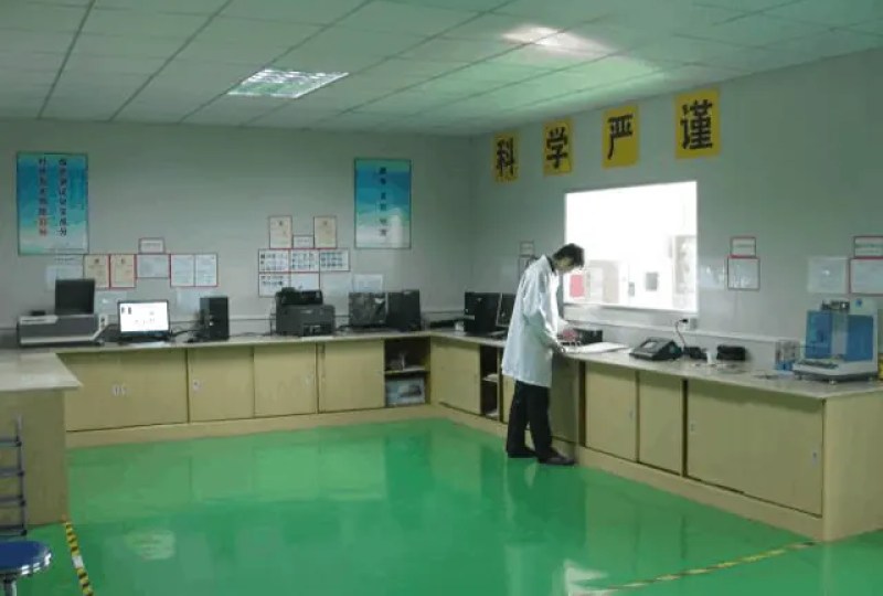
RFPCB and PCBSync share the manufacturing facility shown below. These process photographs illustrate the production environment; they are not evidence that a particular board, material grade or RF performance has been qualified. Request the documentation and inspection scope applicable to your project.


RF filter and duplexer PCB FAQs
Can you guarantee center frequency from the Gerber files alone?
No responsible guarantee can be based on artwork alone. The material construction, process, enclosure and test conditions also affect the result. Define the acceptance target and validate a representative construction through engineering review and measurement.
Is a 50-ohm coupon enough to accept a filter PCB?
It can provide useful evidence about a representative transmission line, but it does not establish the complete filter response. Center frequency, bandwidth, rejection and isolation require the appropriate circuit measurement and agreed reference planes.
Does the calculator design a bandpass filter?
No. It illustrates resonance scaling under a simplified electrical-length model. It does not determine filter order, coupling coefficients, stopband behavior or final dimensions. Use circuit and electromagnetic analysis for those tasks.
What files are needed for an assembled duplexer quote?
Provide fabrication and drill data, the stackup, BOM, placement files, assembly notes and RF test specification. Include mechanical parts, connector details and tuning requirements. Identify customer-supplied items and any fixture that must be developed.
Continue your engineering review
Request a filter or duplexer manufacturing review
Send the stackup, critical geometry and target RF response. Define whether you need bare boards, assembly, tuning or measured modules so the quotation covers the intended scope.
Sources and engineering scope
Manufacturer values apply to the identified grade, test method and construction. Engineering examples on this page are illustrative; they are not measured product results, inventory statements or certification claims. Rogers product names are trademarks of their owner. Keep the applicable datasheet revision with your approved manufacturing package.
Ready for a quotation?
Send your requirements for a material, stackup and manufacturing review. Price and schedule are confirmed for your project.