
PTFE antenna material · Historical reference and project review
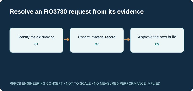
A Rogers RO3730 PCB request often begins with an existing antenna drawing or material reference. RO3730 is identifiable in a manufacturer-authored datasheet revised in July 2012, available through a third-party mirror. This guide uses that document as a historical reference and separates it from the current construction, sourcing and acceptance information needed for an order.
RO3730 is a documented Rogers antenna-grade material associated with PTFE board processing. The historical sheet supports identifying the grade and interpreting its published electrical references. A current manufacturer-hosted specification and current supply were not confirmed for this guide. Obtain those project-specific confirmations before fabrication or approving an alternative; this is not a claim that the grade is discontinued.
RO3730: what the historical record establishes
| Item | Historical reference | What your project still needs |
|---|---|---|
| Document identity | Rogers datasheet, revised 0961 071712, publication 92-162 | Applicable current specification or written manufacturer clarification |
| Process Dk | 3.00 ± 0.06, 10 GHz / 23°C; IPC-TM-2.5.5.5 as printed | Construction-specific model and agreed material acceptance |
| Design Dk | 2.93, 8–40 GHz; differential phase-length method | A model suited to your geometry and frequency |
| Typical Df | 0.0016 at 10 GHz; 0.0013 at 2.5 GHz, both 23°C | Loss allocation for the finished RF path |
| Published construction context | Woven-glass reinforcement; PTFE fabrication route | Core, copper, bonding and hole-processing review |
| Documented copper option | Historical sheet describes rolled copper | The requested foil and its present supply proposal |
| Procurement status | Historical identification only | No stock, lead-time or lifecycle status inferred from the mirror |
Resonance sensitivity explorer
f₂ = f₁ × (L₁/L₂) × √(εeff₁/εeff₂). Hold geometry and coupling assumptions consistent. These are effective permittivities from a transmission-line model, not automatically the published bulk or process Dk. The calculation illustrates sensitivity rather than synthesizing a filter.
Start by recovering the original design record
An old bill of materials may identify the laminate without preserving the thickness, foil or manufacturing notes that made the circuit work. Collect the approved drawing, layer stack, artwork revision and any earlier inspection or RF reports. Check whether the material name appears consistently across those records. A photograph of a finished board or an informal purchase description may help locate records, but it does not establish the complete construction.
Write down what is known and what is missing before requesting a repeat build. If the original design owner is available, ask which features were tuned and which dimensions were fixed by the enclosure. That information can guide a useful engineering review even when the material documentation needs updating. Avoid filling gaps with assumptions from another Rogers antenna grade.
Use the historical datasheet within its limits
The manufacturer-authored RO3730 datasheet mirrored by PW Circuits carries revision 0961 071712 and publication number 92-162. Its property table distinguishes process and design Dk and identifies the two Df test frequencies shown above. The mirror's upload directory is not the date of the manufacturer's technical revision.
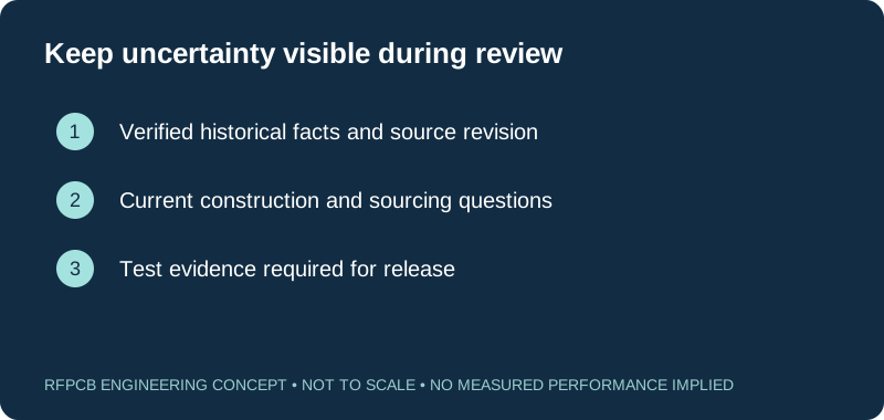
Use this document to interpret an existing specification and form precise questions. Request confirmation of the material description and applicable limits for the proposed order. Do not treat historical inventory language, certifications or available configurations as present-day commitments. An inaccessible current product document does not prove either continued production or discontinuation. If current confirmation remains unavailable, keep that uncertainty explicit and decide whether the project should investigate a documented alternative.
Preserve the antenna structure when assessing a repeat build
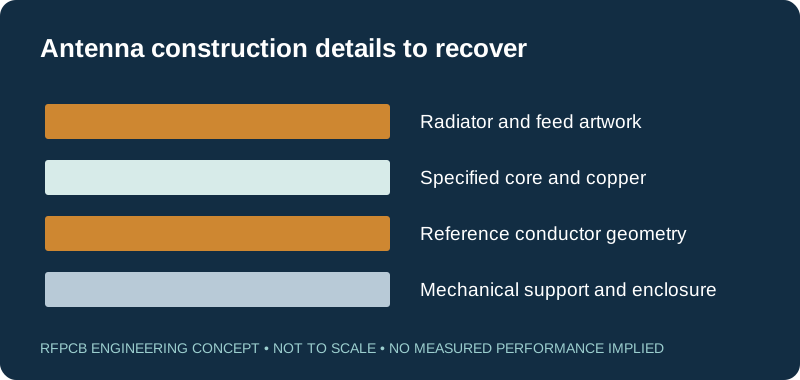
The board's role in the antenna should determine what must be recovered and controlled. Identify the radiator, feed, ground geometry and mechanical surroundings. A replacement board that matches the outer dimensions can still represent a different RF structure if dielectric spacing, copper or nearby conductors change. State whether the first goal is an equivalent repeat build or an intentionally redesigned antenna.
For equivalence work, retain a known sample and its measurement conditions where possible. For redesign work, define the new acceptance requirements before choosing a replacement material. These are different experiments and should not share an unexplained pass criterion. Record how the antenna is mounted and enclosed during testing so an apparent material difference is not actually a change in the surrounding assembly.
Keep process Dk, design Dk and effective permittivity separate
Rogers' discussion of Dk measurement methods explains why different reported values can serve different purposes. A process reference and a design reference do not represent two manufacturing states of the same sample. Effective permittivity also depends on the electromagnetic structure. Use a value appropriate to the selected model instead of entering every number from the material table interchangeably.
The resonance explorer illustrates sensitivity only. With a hypothetical unchanged path and effective permittivity changing from 2.50 to 2.55, a 2.4 GHz reference becomes approximately 2.3764 GHz. These effective values are not assigned to RO3730. The example helps expose the size of a possible tuning concern; it does not establish the board's antenna resonance, bandwidth, radiation pattern or acceptable manufacturing tolerance.
Ask for a PTFE construction review with the hole schedule
Identify the actual dielectric layers, any bonding material, copper and finished board thickness. Include plated and nonplated holes and explain which interconnects affect RF current or mechanical attachment. The historical material description points to a PTFE fabrication route, but it does not qualify the process for your proposed multilayer construction.
Have the fabricator identify the applicable preparation and bonding guidance before release. If a new layer count or adhesive is proposed, review it as a construction change. Distinguish a simple two-sided antenna board from a board with embedded feeds and multiple transitions. The multilayer RF guide can help capture reference-plane and transition requirements. Record unresolved process questions rather than importing generic limits from an unrelated laminate family.
Make copper and interfaces part of the acceptance plan
A historical laminate selection may have been made together with a particular foil, finish or connector arrangement. Preserve that relationship in the inquiry. If the copper specification is missing, identify it as a gap rather than assuming that any nominal copper weight produces the same behavior. Thickness alone does not describe every feature of an RF conductor.
Define whether your acceptance result includes the connector launch, feed network or entire antenna assembly. When requesting PIM evidence, identify the test article, stimulus and required result; a historical laminate reference is not an assembled-product PIM certificate. Keep the interface condition and any rework linked to each sample. This makes subsequent investigation possible if a repeated build changes while the material designation appears unchanged.
Evaluate an alternative without declaring it equivalent in advance
If RO3730 sourcing cannot be resolved for the required construction, begin with a list of requirements rather than a substitute part number. Include the electrical model, dimensions that may change, environmental conditions and needed manufacturing evidence. A material with a similar nominal Dk may be worth evaluating, but that single property does not preserve the antenna or feed response.
Request separate proposed stackups and quotations for the candidates. Record any foil, finish, bonding or geometry changes, then build the qualification plan around their effects. The RO4533 / RO4535 guide discusses a different antenna-material family; it is a comparison starting point, not a replacement approval. Keep the original baseline available so the reason for accepting an alternative remains traceable.
Use targeted measurements to close the missing evidence
Choose test structures based on the uncertainty. A uniform line may help investigate propagation or loss; a representative antenna is needed when the concern is radiation behavior. Specify the operating band, reference planes and physical arrangement before testing. Keep the raw data and any corrections together, with the sample and construction revision clearly identified.
If historical reports are incomplete, say which comparisons remain possible and which must be repeated. A good new measurement can establish a present baseline without pretending to reconstruct every detail of the older test. Use the report guide to define the record and the prototype guide to choose the build. Agree the decision after testing before the experiment begins.
Submit an inquiry that can lead to a concrete decision
Attach the existing material callout, historical source, recovered stackup and manufacturing data. State the requested quantities, test scope and whether an alternative construction may be proposed. Flag missing information that affects release, particularly document applicability, material identity and supply. This lets the response address a specific engineering request instead of providing a generic material description.
The next decision may be to confirm the requested construction, obtain further manufacturer clarification, or qualify a defined alternative. Record the owner of that decision and the conditions required for approval. Only then freeze the manufacturing package for the intended build. This page supplies a careful route through an older material reference; it does not provide a present inventory promise, an automatic substitute or a finished-antenna performance guarantee.
Prepare a reviewable engineering request
Check only the requirements you have actually documented. This list records readiness; it does not inspect your files or certify a design. Missing information is useful: identify it explicitly so the engineering review can resolve it before a production release.
These inputs are processed in your browser and are not submitted by this tool. The downloaded summary is a plain-text planning record. Use the secure quote form to send files; request an NDA first if your project requires one.
Manufacturing context
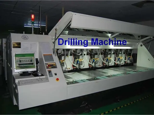
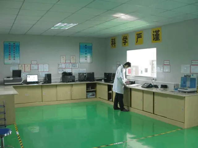
RFPCB and PCBSync share the manufacturing facility shown below. These process photographs illustrate the production environment; they are not evidence that a particular board, material grade or RF performance has been qualified. Request the documentation and inspection scope applicable to your project.

RO3730 PCB questions
Is RO3730 a verified material name?
Yes. The linked manufacturer-authored 2012 datasheet identifies RO3730. It supports historical identification and reference interpretation. A current specification and supply proposal still need confirmation for your order.
Does this page say RO3730 is discontinued?
No. The historical source and the absence of a confirmed current document here do not establish lifecycle status. Ask for current manufacturer or supply-chain confirmation for the requested construction.
Can I use the historical Df value in a current loss guarantee?
No. It is a material reference under a stated test condition. Finished-route loss also depends on geometry, copper and interfaces, and the applicable current construction must be confirmed.
Can another Dk 3 material replace RO3730?
It can be evaluated, but similar nominal Dk is not sufficient for approval. Compare the complete construction, permitted geometry changes and antenna or interconnect evidence required by the design.
Continue your engineering review
Review an RO3730 drawing or material inquiry
Share the original callout, available records, requested construction and acceptance needs. Mark current documentation or supply questions and state whether a documented alternative may be evaluated.
Sources and engineering scope
- Rogers RO3730 manufacturer datasheet, revision 0961 071712, historical PW Circuits mirror
- Rogers: Managing PCB Materials Dielectric Constant (Dk), measurement and design context
- Keysight: Removing Unwanted Effects from the Measurement, fixture and reference-plane context
Manufacturer values apply to the identified grade, test method and construction. Engineering examples on this page are illustrative; they are not measured product results, inventory statements or certification claims. Manufacturer and product names belong to their respective owners. Keep the applicable datasheet revision with your approved manufacturing package.
Ready for a quotation?
Send your requirements for a material, stackup and manufacturing review. Price and schedule are confirmed for your project.