
Antenna laminates · Grade and revision control
Rogers RO4533 PCB requests need a named antenna construction, copper specification and RF acceptance plan. This combined guide also covers RO4535 for drawings that specify that grade. The currently retrieved Rogers RO4500 datasheet lists RO4533 and RO4534; RO4535 references below are explicitly historical. Confirm the applicable material document and supply proposal before release.
RO4533 and RO4535 belong to the RO4500 thermoset antenna-material family, but they are separate grades. Use the actual grade, foil and thickness in the circuit model and purchase description. Historical RO4535 data can help interpret an existing drawing; it neither establishes present availability nor authorizes substitution with RO4533.
RO4533 and RO4535: references with their document scope
| Review item | RO4533 | RO4535 |
|---|---|---|
| Reference document | Rogers-hosted RO4500 PDF, revision 081326 | Manufacturer-authored mirror, revision 062017 |
| Material family | Ceramic-filled, glass-reinforced hydrocarbon thermoset | Same historical family; a different grade |
| Process Dk | 3.3 ± 0.08; IPC-TM-650 2.5.5.5 | Historical table: 3.44 ± 0.08; same method |
| Dk table conditions | 10 GHz / 23°C and 2.5 GHz are listed | 10 GHz / 23°C and 2.5 GHz are listed |
| Typical Df at 2.5 / 10 GHz | 0.0020 / 0.0025 at 23°C | Historical: 0.0032 / 0.0037 at 23°C |
| Foil and model | Confirm standard or LoPro construction | Do not assume the RO4533 model transfers |
| Procurement decision | Confirm requested construction and current quote | Confirm document applicability and supply explicitly |
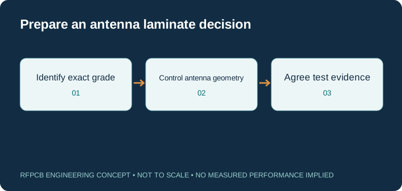
Route mismatch to phase and delay
Delay = length mismatch × √εeff / c; phase = 360 × frequency × delay. The effective permittivity belongs to the actual geometry, not a generic material family. This nondispersive estimate excludes bends, transitions and different route constructions.
Keep the two grade identities separate
An existing drawing may say RO4533 or RO4535 even when a purchasing list groups them under RO4500. Preserve the complete designation in the request. The Rogers-hosted family datasheet retrieved for this guide has a property table for RO4533 and RO4534. The 2017 manufacturer datasheet hosted by Elco includes RO4535. That document difference is a reason to request clarification, not evidence of a product's current stock or lifecycle status.
When ordering against an older design, attach its approved material specification and identify any acceptable alternatives. Ask for a written proposed construction if the requested grade cannot be confirmed. Keep engineering review separate from the administrative act of finding a familiar material name in a catalog.
Choose the antenna requirement before the laminate option
Antenna material selection begins with the required band, bandwidth, radiation behavior and mechanical envelope. Describe the radiator and feed arrangement, the mounting surface, nearby metal and enclosure. A material data table cannot determine the final antenna gain or guarantee the assembled response. State which result is most sensitive to the construction so the review can focus on useful evidence.
For an array, identify the feed paths that need consistent phase and amplitude. For a single element, highlight tuning features and the interface to the feed. If the product has several operating configurations, list the representative conditions that the prototype must cover. This prevents an isolated bare-board measurement from becoming the only acceptance evidence for an antenna that will operate inside a substantially different assembly.
Treat foil choice as part of the electrical construction
The RO4500 datasheet qualifies its PIM discussion by copper choice and test construction, and its LoPro note distinguishes the modified bonding resin from the base-material table. This is why a foil option belongs in the model and controlled drawing. The published PIM context is not a guaranteed result for a populated antenna with connectors, joints and mounting hardware.
Identify the proposed copper on each face, finished thickness and surface treatment. If the quotation changes the foil, ask which electrical and dimensional assumptions need review. For a PIM-sensitive assembly, state the requested test configuration and acceptance criterion separately from the laminate requirement. Retain the finished assembly condition with the result. An entry that simply says “low PIM material” leaves too much uncertainty about the actual object and method being accepted.
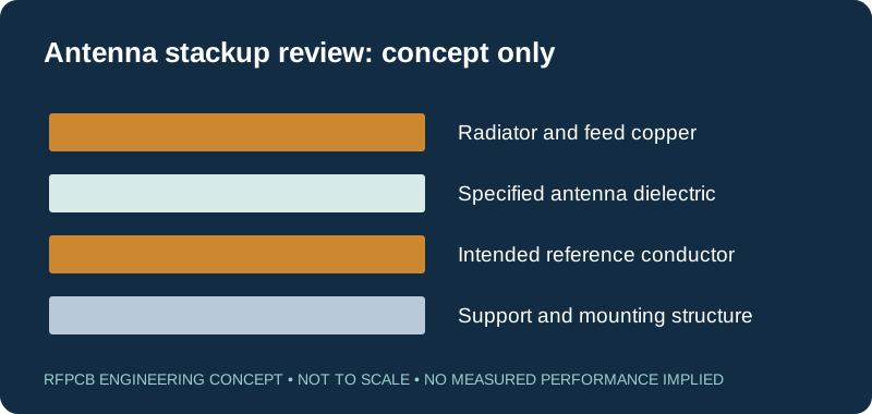
Use phase sensitivity to prioritize feed-path review
The delay explorer estimates how an entered route-length difference affects delay and phase under a common effective-permittivity assumption. It is useful when deciding whether an apparently small geometry change deserves closer attention. It does not derive effective permittivity from the material name or include discontinuities, coupling and dispersion.
As an illustrative calculation, enter 2.5 GHz, effective permittivity 2.8 and a 1 mm path mismatch. The result is about 5.58 ps and 5.02 degrees. These inputs are hypothetical and are not a RO4533 measurement. For a real array, use the model of the actual feed structure, and consider component and transition differences as well as trace length. Equal centerline lengths do not prove equal electrical paths if the cross-sections or loading differ.
Give manufacturing a controlled antenna drawing
Mark the radiator dimensions, feed widths, coupling gaps and other features that the model treats as critical. Distinguish the nominal artwork from the acceptance dimension after processing. Include the reference plane, dielectric spacing and any intentional copper-free regions. Avoid relying on a board outline alone to communicate the electromagnetic structure.
Ask for DFM feedback before releasing a tightly tuned pattern. If a proposed adjustment changes a critical region, route it back to the design owner rather than treating it as an invisible fabrication correction. Include tolerances only where they are supported by the circuit margin and manufacturing review. A longer list of arbitrary tight dimensions can increase inspection effort without resolving the feature that actually controls the antenna response.
Review multilayer and hybrid proposals as complete stacks
Some antenna designs use a dedicated radiator layer and a more complex feed structure below it. If the proposed board combines materials, identify every dielectric encountered by the sensitive fields and each transition between reference conductors. The name of the top core does not describe the complete behavior of an embedded feed or plated transition.
Prepare a layer drawing with bonding materials, conductor functions and finished thickness targets. Review mechanical support, registration and assembly conditions alongside electrical requirements. If a supplier proposes a different bonding construction, compare the new model and qualification scope before accepting it. The hybrid-stackup guide helps organize that review. A hybrid is a construction option to evaluate, not an automatic performance match or fixed percentage cost saving.
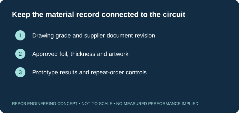
Make the prototype representative of the antenna decision
Choose test articles that distinguish the radiator, feed and connection questions. A line coupon can help investigate an interconnect, but it cannot replace antenna measurements when radiation behavior is the acceptance requirement. Record the sample revision, construction and test environment so the result can be compared with the simulation and later builds.
Define the next action for each plausible result. If the feed loss meets its allocation but the antenna response misses the band, the next experiment should target the unresolved mechanism. If several construction changes are trialed together, report them as a complete revision. Use the prototype planning guide to keep the experiment bounded and the test-report guide to define useful records.
Handle an RO4535 substitution as an engineering change
An alternative offered for an RO4535 drawing needs more than a nearby nominal dielectric constant. Compare the complete material identity, applicable properties, copper and dimensions. Determine whether flame-related or other product requirements were part of the original selection, and request the relevant current material documentation rather than assuming a historical description applies to the finished board.
Document which artwork changes are permitted and which results must be requalified. Preserve the original baseline measurements where available. If the motivation is delivered cost or supply, include the engineering effort and test schedule in the decision. A purchasing substitution should follow the approved change record; it should not become the first place that the design team learns its material construction has changed.
Request a quote that states what is actually being supplied
Send the specified grade, source document, layer stack, copper and finish requirements with the manufacturing files. Include quantity, mechanical constraints and requested inspection or RF evidence. For an older material reference, flag document applicability and sourcing as explicit questions. Request confirmation for the particular thickness and foil instead of interpreting this page as an inventory statement.
The useful quotation response identifies the proposed construction, unresolved requirements and delivered scope. Review that response with the person responsible for antenna performance before approving production. The DFM checklist and cost worksheet can organize the information. Keep the final material and artwork revisions together so a repeat order refers to the tested design rather than a loosely described material family.
Prepare a reviewable engineering request
Check only the requirements you have actually documented. This list records readiness; it does not inspect your files or certify a design. Missing information is useful: identify it explicitly so the engineering review can resolve it before a production release.
These inputs are processed in your browser and are not submitted by this tool. The downloaded summary is a plain-text planning record. Use the secure quote form to send files; request an NDA first if your project requires one.
Manufacturing context
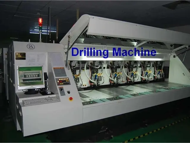
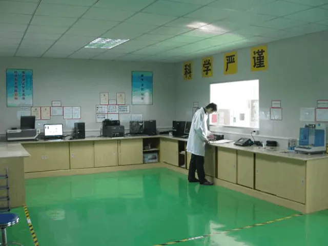
RFPCB and PCBSync share the manufacturing facility shown below. These process photographs illustrate the production environment; they are not evidence that a particular board, material grade or RF performance has been qualified. Request the documentation and inspection scope applicable to your project.

RO4533 / RO4535 PCB questions
Are RO4533 and RO4535 interchangeable?
No. They are different grades with different reference properties. Review the actual stackup, foil, model and original acceptance requirements before proposing a change.
Does an older RO4535 datasheet prove current supply?
No. The linked historical manufacturer document identifies the material and its reference data. Confirm document applicability, requested construction and supply for the project. Its age alone also does not prove discontinuation.
Does low-PIM laminate guarantee a low-PIM antenna?
No. Material data describes a stated specimen and method. Define the completed assembly and its PIM test requirement, including interfaces and mounting conditions, if that result matters to acceptance.
Can the delay tool set my antenna feed lengths?
It only converts an entered mismatch into a simplified delay and phase estimate. Use geometry-specific models and the complete network requirements to design the feed, then verify the representative assembly.
Continue your engineering review
Request an antenna-material construction review
Share the grade on your drawing, document revision, antenna stackup and test objectives. Identify RO4535 sourcing or substitution questions explicitly so the proposal can be reviewed before release.
Sources and engineering scope
- Rogers RO4500 datasheet: retrieved revision 1597 081326; RO4533 and RO4534 property table
- Rogers RO4500 manufacturer datasheet, revision 1327 062017, historical Elco-hosted copy including RO4535
- Rogers: Managing PCB Materials Dielectric Constant (Dk), measurement and design context
Manufacturer values apply to the identified grade, test method and construction. Engineering examples on this page are illustrative; they are not measured product results, inventory statements or certification claims. Manufacturer and product names belong to their respective owners. Keep the applicable datasheet revision with your approved manufacturing package.
Ready for a quotation?
Send your requirements for a material, stackup and manufacturing review. Price and schedule are confirmed for your project.