
Antenna directory · Radiator, feed and installation
PCB antenna resources connect the radiating structure to its feed network and installed environment. Choose a guide according to the antenna system you are developing. This directory helps organize the review without treating a laminate value or ideal wavelength as a finished antenna design.
Start with the antenna function, operating band and installation. Use the antenna guide for the board and feed, the phased-array guide for coordinated elements, and the relevant radio application guide for system context. Define measurement conditions for the intended assembly before judging material or layout changes.
Find the antenna resource that fits the project
| Design task | Destination | Bring to the review |
|---|---|---|
| Printed radiator and feed | Antenna PCB | Band, geometry and installed surroundings |
| Multiple coordinated elements | Phased-array PCB | Array arrangement and feed requirements |
| Connected-device antenna | RFID, IoT and LoRa | Radio configuration and product enclosure |
| High-frequency radio feed | 5G and millimeter-wave | Transitions, loss and phase limits |
| RF measurement interface | Test fixtures | Launch geometry and reference planes |
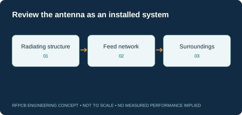
Start with the dedicated antenna guide
Open antenna PCB for the core discussion of printed radiators, feeds and material selection. Describe the intended antenna configuration and operating band before selecting a substrate. Mark the dimensions and interfaces that are fixed by the product. The guide supports a construction review; the final antenna needs analysis and measurement appropriate to its installation.
Separate feed questions from radiation questions
An antenna project can contain both a transmission path and a radiating structure. Use the RF loss guide to organize feed attenuation, launches and other passive contributions. Keep those boundaries separate from the antenna measurement. This helps reviewers understand whether a proposed change addresses feed loss, input matching, radiation behavior or several coupled effects.
Use the array route for coordinated elements
The phased-array guide addresses questions that arise when multiple elements operate together. Supply the array arrangement, feed architecture and required operating conditions. Its ideal geometry tool is a planning aid with stated assumptions. It does not replace evaluation of the actual elements, coupling, feed differences and installed assembly.
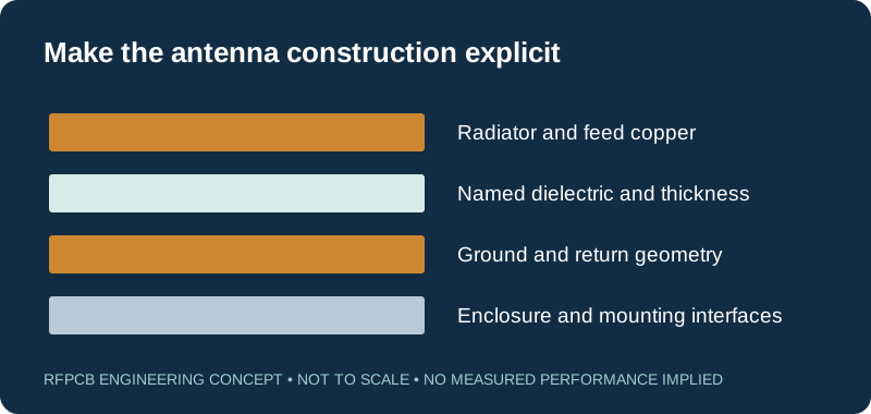
Add the connected-product context
For a compact radio product, use RFID, IoT and LoRa PCB alongside the antenna guide. Specify the exact technology and operating configuration instead of treating all connected devices as one antenna problem. Include the enclosure, nearby circuitry and intended mounting. A board measured in isolation may not represent the finished product environment.
Choose the appropriate high-frequency application
Use 5G and millimeter-wave PCB when the feed and transitions require that context, or 77 GHz radar PCB for the corresponding sensing system. State actual band edges and performance limits. The application name helps locate resources, while the design and installed conditions determine the project requirements.
Keep material comparisons construction-specific
The material selection guide helps compare grade, copper and dielectric thickness. Use the property table with its method and frequency labels. Do not select an antenna laminate solely by a family-wide loss claim. Retain the exact proposed construction so changes to the electrical model can be reviewed coherently.
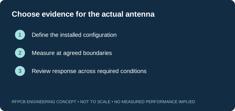
Define how the antenna will be measured
Visit test and measurement PCB for launch and fixture questions and the report guide for measurement records. State the installed configuration, boundaries and required quantities. A good input match is one useful observation, but the product may require additional antenna or system evidence beyond that single result.
Prepare an antenna-specific manufacturing brief
Send the layout, material candidate, feed structure and mechanical context through project review. Mark critical outlines, gaps and launch dimensions, then identify the evidence expected from fabrication versus assembled testing. If tuning changes are permitted, state that scope. This makes the request actionable without presenting an ideal electrical-length calculation as fabrication-ready artwork.
Prepare a reviewable engineering request
Check only the requirements you have actually documented. This list records readiness; it does not inspect your files or certify a design. Missing information is useful: identify it explicitly so the engineering review can resolve it before a production release.
These inputs are processed in your browser and are not submitted by this tool. The downloaded summary is a plain-text planning record. Use the secure quote form to send files; request an NDA first if your project requires one.
Manufacturing context
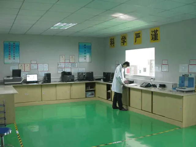
RFPCB and PCBSync share the manufacturing facility shown below. These process photographs illustrate the production environment; they are not evidence that a particular board, material grade or RF performance has been qualified. Request the documentation and inspection scope applicable to your project.


Antenna resource questions
Does the antenna directory provide a ready-to-build design?
No. It routes you to guides and planning tools. A finished design requires its own geometry, installation review and appropriate validation.
Should I use the phased-array guide for a single radiator?
Start with the antenna PCB guide for a single radiator and feed. Use the array guide when coordinated elements and array-specific requirements are part of the system.
Can return loss alone establish antenna performance?
Return loss describes an input condition at defined boundaries. Decide what additional radiation or system evidence is needed for the intended application.
What should accompany an antenna RFQ?
Provide the band, layout, material and copper requirements, mechanical surroundings, critical tolerances and the intended measurement scope.
Continue your engineering review
Connect antenna geometry to the installed requirement
Share the board and its surrounding mechanical arrangement, not only the laminate name. Identify critical dimensions and the measurements needed to approve the intended configuration.
Sources and engineering scope
- RFPCB antenna construction and installed-context guide
- RFPCB phased-array guide and ideal-tool assumptions
- RFPCB RFID, IoT and LoRa application guide
- RFPCB test and measurement fixture guide
- RFPCB material selection workflow
Manufacturer values apply to the identified grade, test method and construction. Engineering examples on this page are illustrative; they are not measured product results, inventory statements or certification claims. Manufacturer and product names belong to their respective owners. Keep the applicable datasheet revision with your approved manufacturing package.
Ready for a quotation?
Send your requirements for a material, stackup and manufacturing review. Price and schedule are confirmed for your project.