
RF laminate comparison · Exact grades matter
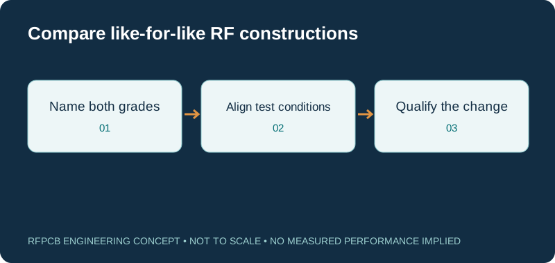
Rogers vs Taconic RF35 becomes a useful engineering comparison when the Rogers grade is named. This page compares RO4350B with RF-35: a reinforced hydrocarbon/ceramic thermoset and a ceramic-filled, woven-glass-reinforced PTFE material. Review the test conditions, proposed construction and qualification work before treating either as an alternative.
RO4350B and RF-35 can both be considered for RF circuitry, but similar nominal dielectric constants do not make them drop-in replacements. Compare impedance and loss on the actual stackup, review the different processing routes, and qualify critical dimensions and RF acceptance. RF-35, RF-35TC and RF-35HTC are different material designations.
RO4350B versus RF-35: reference values with context
| Question | Rogers RO4350B | Taconic / AGC RF-35 |
|---|---|---|
| Resin / reinforcement | Hydrocarbon-ceramic thermoset with glass reinforcement | Ceramic-filled PTFE with woven glass |
| Dk reference | Process 3.48 ± 0.05 at 10 GHz; see 4 mil exception below | Nominal 3.50 in AGC reference guide; mirrored RF-35 datasheet gives 3.50 at 1.9 GHz |
| Published design Dk | 3.66 reference, differential phase-length method | Request the construction-specific model; do not import a different RF-35-family grade |
| Typical Df references | 0.0037 at 10 GHz | 0.0018 at 1.9 GHz in the mirrored manufacturer datasheet |
| Can these Df entries rank board loss? | No: test frequency and completed route must be comparable | No: this is not a measured side-by-side 10 GHz comparison |
| Fabrication review | Thermoset processing and compatible bonding construction | PTFE hole preparation and approved bonding construction |
| Commercial decision | Quote the exact core, foil, finished board and tests | Confirm current grade, thickness, supplier revision and availability |
Resonance sensitivity explorer
f₂ = f₁ × (L₁/L₂) × √(εeff₁/εeff₂). Hold geometry and coupling assumptions consistent. These are effective permittivities from a transmission-line model, not automatically the published bulk or process Dk. The calculation illustrates sensitivity rather than synthesizing a filter.
Why this comparison names RO4350B
Rogers is a manufacturer, not one electrical material. A comparison against RO3003, RO4003C or another grade would answer a different question. RO4350B is the named baseline here so that the reader can connect the decision to an actual fabrication drawing. If your approved board uses another grade, use its own model and requirements instead of transferring this conclusion.
The same precision is needed on the other side. RF-35 is not shorthand for every laminate whose designation begins with RF-35. Keep the manufacturer, complete grade name, thickness and copper specification together. An RFQ that says only “Rogers or Taconic” leaves purchasing and fabrication without a clear definition of an acceptable substitution.
Read the reference table before comparing the numbers
The linked AGC manufacturer reference guide identifies RF-35 as a ceramic/PTFE woven-glass construction with nominal Dk 3.50. The additional RF-35 manufacturer datasheet is hosted as a mirror; its 1.9 GHz values are reference information, not confirmation of the latest procurement specification. Obtain the applicable revision before ordering.
The RO4000 datasheet lists the RO4350B values shown above, with an important exception: its 4 mil RO4350B construction has process Dk 3.33 ± 0.05. The document also distinguishes standard and LoPro constructions. These details are why a material comparison must carry thickness, foil and test-method context instead of presenting a single universal number for every board.
Similar Dk does not preserve impedance automatically
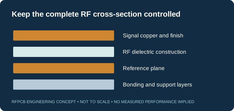
Impedance depends on trace geometry, dielectric spacing, copper profile and the fields surrounding the conductor. Process Dk is measured by a stated material test. Effective permittivity describes propagation in a particular structure. A surface microstrip and an embedded stripline on the same material do not necessarily use identical propagation assumptions.
Use the sensitivity explorer with effective values from your chosen transmission-line model. For an illustrative unchanged 10 mm resonator, increasing effective permittivity from 3.00 to 3.06 shifts a 10 GHz first-order estimate to about 9.9015 GHz. This arithmetic is not a prediction that either laminate will produce those values. It shows why copying artwork alone does not establish equivalence.
Compare loss at the operating band and reference planes
A smaller Df number from a different test frequency is not enough to select a lower-loss finished board. Set the operating band, route length and permitted insertion loss first. Identify whether the requirement includes connector launches, matching components, switches or only the uniform transmission line. The measurement needs the same boundaries as the requirement.
For a material trial, compare equivalent foil and surface-finish conditions, or explicitly document why they differ. A routing or connector change may explain more of the measured difference than the laminate. Retain both the raw measurement and any corrected result so that the qualification record makes the comparison reproducible rather than turning it into an unexplained brand ranking.
Manufacturing changes need their own review
The thermoset and PTFE routes have different process considerations, particularly around hole preparation, bonding and dimensional control. Ask the fabricator to review the entire proposed construction, including the dielectric layers traversed by plated holes. A two-layer coupon is useful evidence for that coupon; it does not automatically qualify a more complex multilayer build.
Provide the layer stack, hole schedule, minimum finished features and any critical edge geometry. Identify whether the assembly requires a particular thermal history or repeated rework. The useful result of DFM is a documented construction and set of agreed limits. It is not a blanket assertion that every thickness and layer count in a material family can be produced identically.
Build the commercial comparison around delivered scope
Request quotations against the same quantity, acceptance criteria and delivery basis. Record setup charges, material allocation, electrical testing, special coupons and assembly separately. A prototype order may be driven by fixed preparation cost, while a production order may be more sensitive to panel use and recurring inspection. Neither case is captured by comparing only the price of a laminate sheet.
Include the cost of evaluating a substitution: model updates, representative prototypes, measurements and engineering approval. The RF PCB cost worksheet helps expose entered assumptions. Use the material-change break-even guide if lower delivered cost is the main reason to reopen an already qualified design.
Choose a prototype that can answer the actual question
Define the most sensitive features before laying out a comparison coupon. A filter may need its resonators, coupling gaps and launches represented. An amplifier board may depend on grounding, thermal paths and component placement. A long interconnect may need enough uniform line length to separate distributed behavior from launch effects.
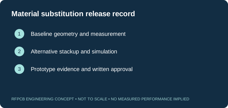
Keep the board revision, measured geometry, material identity and test setup linked to each sample. When possible, change one factor at a time. If multiple factors must change, label the trial as a construction comparison rather than attributing every difference to material Df. Decide the acceptance thresholds before reviewing the results, so that a convenient result does not redefine the original engineering requirement.
Protect repeat orders from silent substitutions
An approved alternative belongs in the controlled manufacturing package. Identify exactly which grade and construction were accepted, which artwork revision was tested, and which changes require notification. An internal purchasing note without the corresponding drawing revision is easy to lose when the next order is placed or a different engineer reviews the project.
If current material availability changes, reopen the specific approval rather than accepting a generic equivalence statement. Ask for the proposed construction and affected parameters in writing. Keep any remaining uncertainty visible in the first-article plan. This gives procurement a practical decision path without implying that a material name, nominal Dk or previous supplier relationship guarantees RF performance.
Prepare the material review and quotation
Start with the intended application, operating band and the problem you need to solve: loss, dimensions, reliability, cost or availability. Attach the current stackup, copper and finish requirements, Gerber or equivalent manufacturing data and the selected tests. State whether the existing artwork must remain unchanged or whether a revised geometry is acceptable.
For grade-specific manufacturing context, continue to RO4350B PCB and Taconic PCB material selection. Use the checklist below to distinguish completed requirements from open questions. The next step is a construction-specific review with comparable commercial scope, followed by the evidence needed to approve production.
Prepare a reviewable engineering request
Check only the requirements you have actually documented. This list records readiness; it does not inspect your files or certify a design. Missing information is useful: identify it explicitly so the engineering review can resolve it before a production release.
These inputs are processed in your browser and are not submitted by this tool. The downloaded summary is a plain-text planning record. Use the secure quote form to send files; request an NDA first if your project requires one.
Manufacturing context
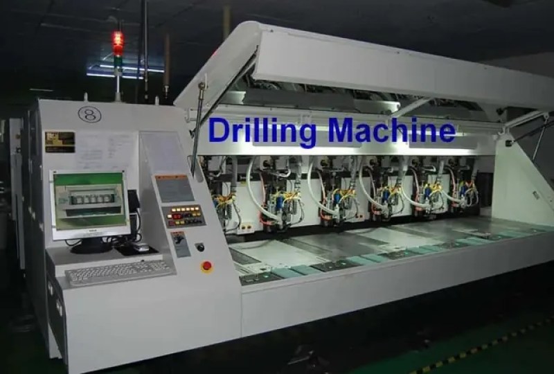
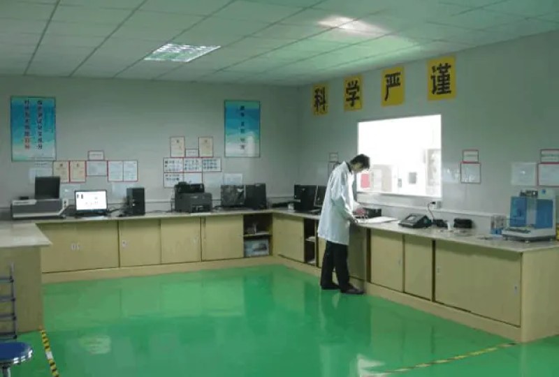
RFPCB and PCBSync share the manufacturing facility shown below. These process photographs illustrate the production environment; they are not evidence that a particular board, material grade or RF performance has been qualified. Request the documentation and inspection scope applicable to your project.

RO4350B vs RF-35 questions
Is RF-35 the same as RF-35TC?
No. The full grade designation matters. Do not transfer RF-35TC or RF-35HTC thermal and electrical values to RF-35. Request the named manufacturer datasheet and confirm the construction available for your project.
Does RF-35 have half the loss of RO4350B?
That conclusion cannot be drawn from the two Df entries here: the referenced RF-35 and RO4350B values use different frequencies. Finished-path loss also includes conductor and interface effects. Use comparable models and measurements at the operating band.
Can RFPCB quote both constructions from one package?
Submit the baseline drawing and specify that the alternative is for engineering comparison. Identify fixed constraints and any permitted changes. Manufacturing feasibility, material availability, commercial scope and qualification requirements must be reviewed for each proposed construction.
Will the resonance tool choose the right laminate?
No. It illustrates the sensitivity of a simplified resonant length to effective permittivity and dimension changes. It does not model coupling, temperature, processing variation or the complete circuit. Material selection also needs fabrication and acceptance requirements.
Continue your engineering review
Request a like-for-like material review
Share the named grades, approved baseline and the requirement driving the change. Include your stackup and acceptance scope so the engineering response can identify the construction, evidence and quotation assumptions that need agreement.
Sources and engineering scope
- Rogers RO4000 manufacturer datasheet: conditions and thickness exceptions
- AGC manufacturer IPC slash-sheet reference guide, July 2025
- AGC/Taconic RF-35 manufacturer datasheet, third-party hosted mirror; confirm current revision
Manufacturer values apply to the identified grade, test method and construction. Engineering examples on this page are illustrative; they are not measured product results, inventory statements or certification claims. Manufacturer and product names belong to their respective owners. Keep the applicable datasheet revision with your approved manufacturing package.
Ready for a quotation?
Send your requirements for a material, stackup and manufacturing review. Price and schedule are confirmed for your project.