
Medical electronics · Controlled manufacturing information
Medical RF PCB manufacturing starts with a clear description of the board, its electrical interfaces and the records your project requires. Use this guide to prepare a reviewable fabrication package for wireless circuitry, sensitive analog paths or ultrasound front-end electronics.
Specify the exact construction, critical geometry, traceability and acceptance evidence for your medical electronics PCB. A manufactured bare board and its inspection records do not establish end-product medical-device qualification. The product owner must define the applicable system requirements and approve the completed equipment.
Medical electronics: translate circuit needs into fabrication information
| Board region | Manufacturing information | Separate product-level evidence |
|---|---|---|
| Wireless RF path | Frequency band, controlled impedance, laminate and launch geometry | Assembled radio and enclosure testing |
| Ultrasound receive path | Sensitive nets, reference planes and channel geometry | Front-end noise and channel behavior |
| Pulser and power region | Copper, holes, spacing and assembly requirements | Voltage, thermal and protection verification |
| Defined isolation barrier | Approved gaps, slots, copper exclusions and tolerances | Safety assessment of the complete insulation system |
| Traceability | Revision, lot identity and requested retained records | Product configuration and qualification records |
| Change control | Named materials and written substitution rules | Decision on required requalification |
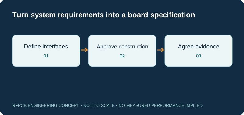
Define the board function before choosing a material
A medical product can contain several boards with very different electrical jobs. A wireless module, an ultrasound receiver and a power distribution board should not inherit the same laminate requirement simply because they share an enclosure. Describe each interface, operating band, signal level and mechanical constraint in the design brief.
Identify what the supplier is quoting: bare-board fabrication, assembly or a defined test service. State who owns the circuit review and system verification. Focus the fabrication discussion on information that can be inspected, controlled and delivered with the board.
Ultrasound front ends are not automatically GHz RF boards
Ultrasound combines an electrical transmit-and-receive front end with acoustic transducers. It should not be described as a GHz radio application merely because its receiver is sensitive. Analog Devices describes an example chain with a transmit/receive switch, low-noise amplification, variable gain, filtering and conversion; its discussion highlights in-band interference and supply-related noise. See the ADI ultrasound system article.
Prepare a channel map that distinguishes pulser connections, receive inputs, clocks and support interfaces. Mark the structures whose dimensions or proximity matter to the design review. The LNA PCB guide provides a separate discussion of sensitive receiver inputs.
Use placement regions and intentional return paths
The MAX14808 layout note recommends a common ground reference for that implementation, regional placement, separation of transmit and receive circuitry, and attention to return paths. This is device-specific guidance, not permission to join grounds across a required safety isolation barrier.
For manufacturing review, provide an annotated layout showing the approved regions and reference planes. Identify sensitive areas where routing changes need engineering approval. A fabrication edit that appears mechanically convenient can affect the intended circuit relationship; preserve the context alongside the copper data so proposed changes receive the right review.
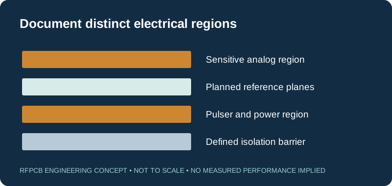
Make isolation requirements explicit in the drawing
Where the design includes an isolation barrier, the product engineering team must supply the approved geometry and construction requirements. Do not ask a board manufacturer to infer the required separation from a generic description such as “medical grade.” Document the relevant copper exclusions, routed slots, hole positions and dimensional tolerances.
Ask how the proposed features will be fabricated and inspected, including slot width and location. Clarify whether later assembly materials, coatings or hardware are part of the specified barrier. Bare-board inspection can check agreed features; it cannot establish the suitability of the complete insulation system or replace the responsible product safety assessment.
Choose and freeze a construction for each electrical task
For an RF path, specify the exact dielectric, finished copper and reference-plane arrangement used by the model. For an analog region, document the construction requirements that matter to routing, assembly and dimensional control. Neither region automatically requires the most expensive available laminate.
Use the stackup library to structure the discussion, then obtain a project-specific drawing. If RO4350B is under consideration, the RO4350B material guide helps identify the information to carry into the RFQ. Reference examples are starting points; the approved stackup should identify the actual materials and thicknesses for this board.
Define traceability as a list of deliverable records
Traceability is useful when it answers a future investigation question. Decide whether you need to connect a delivered board lot to a fabrication revision, material lot, inspection report or shipment. Specify identifiers and record retention expectations during quotation, then confirm what the supplier can provide for the proposed order.
Avoid treating the word “traceable” as a complete contractual requirement. Agree the marking location, readable format and relationship between panel and individual-board identifiers. If serialization is required, include its handling rules. Retain the accepted documentation with your own product configuration records so later comparisons use the correct baseline.
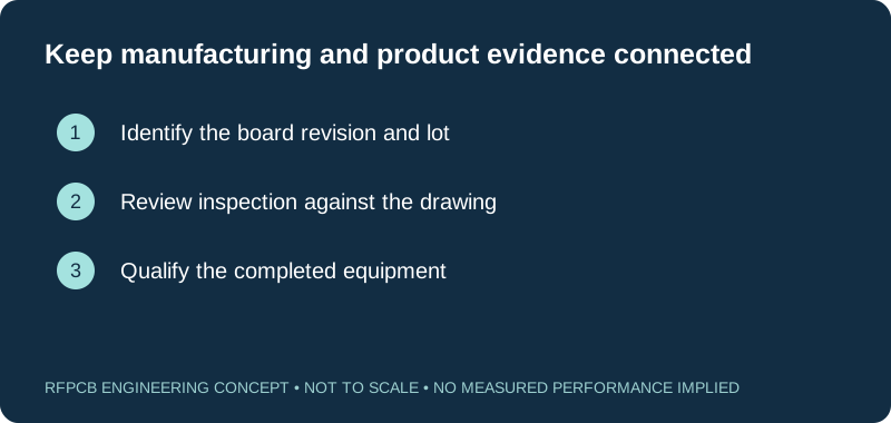
Agree what inspection can demonstrate
Turn critical requirements into an inspection schedule with a feature, method, sample scope and acceptance criterion. Examples include finished thickness, hole dimensions, defined slot locations, electrical continuity and the requested impedance coupon. Distinguish a result measured on a coupon from a result measured on every delivered board.
Use the RF PCB DFM checklist to organize unresolved fabrication questions. If additional evidence is needed, state the required report format before ordering. An inspection record should be interpreted against its stated scope; it does not establish assembled receiver noise, wireless performance or complete equipment qualification.
Carry assembly constraints into the bare-board request
The fabrication drawing should anticipate the planned assembly. Identify finish, mask coverage, exposed pads, component clearances and any areas where marking is restricted. Include assembly drawings when connector alignment, shields or heat-transfer features affect the board construction, even if assembly is being quoted separately.
For dense packages, resolve hole fill, pad treatment and flatness requirements with the fabrication and assembly teams. Define any cleanliness or packaging requirements with an agreed verification method. Concrete process and acceptance information is more useful than a promise of a universally suitable medical board.
Control changes and compare complete quotation scope
A material substitution, revised isolation feature or changed inspection scope should follow a recorded review. Keep the approved files, open questions and final supplier responses under one revision. State who may approve a proposed change and how the resulting manufacturing package will be updated.
Use the RF PCB cost calculator to separate fabrication assumptions from extra inspection, documentation and qualification work. Submit that scope through the project quote form. Ask for a reviewed proposal against your actual package; this page does not claim a particular certification, available stock or approval for a finished medical device.
Prepare a reviewable engineering request
Check only the requirements you have actually documented. This list records readiness; it does not inspect your files or certify a design. Missing information is useful: identify it explicitly so the engineering review can resolve it before a production release.
These inputs are processed in your browser and are not submitted by this tool. The downloaded summary is a plain-text planning record. Use the secure quote form to send files; request an NDA first if your project requires one.
Manufacturing context
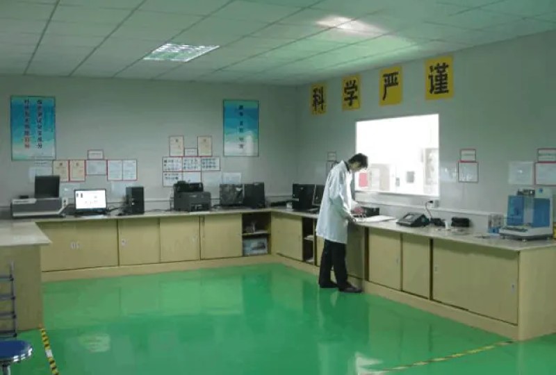
RFPCB and PCBSync share the manufacturing facility shown below. These process photographs illustrate the production environment; they are not evidence that a particular board, material grade or RF performance has been qualified. Request the documentation and inspection scope applicable to your project.


Medical RF PCB manufacturing FAQs
Does a medical RF PCB come with medical-device approval?
No. A bare board and its agreed manufacturing records are only part of a product development package. End-product qualification and any required approvals depend on the completed equipment, intended use and requirements established by its responsible owner.
Does every ultrasound board need microwave laminate?
No. Select the construction for the actual electrical paths and manufacturing requirements. Ultrasound front-end electronics are distinct from a GHz wireless radio. A mixed product can contain both, with different requirements for each region or board.
Should I split analog and digital grounds?
Do not adopt a universal split-ground rule. Follow the selected devices and the validated return-path plan. The cited MAX14808 note favors a common reference for its implementation; required safety isolation boundaries remain a separate design constraint.
What should I request for repeat-order traceability?
Define the connection you need between delivered boards, drawing revision, material identity and inspection evidence. Agree marking and retained records before release. Reference the approved package in repeat orders and require review of proposed substitutions.
Continue your engineering review
Request a review of your medical electronics PCB package
Send the board function, approved drawing, stackup and required records. Identify open manufacturing questions and the team responsible for end-product qualification.
Sources and engineering scope
- Analog Devices: MAX14808 ultrasonic front-end grounding and layout note
- Analog Devices: compact medical ultrasound and low-noise system design
Manufacturer values apply to the identified grade, test method and construction. Engineering examples on this page are illustrative; they are not measured product results, inventory statements or certification claims. Manufacturer and product names belong to their respective owners. Keep the applicable datasheet revision with your approved manufacturing package.
Ready for a quotation?
Send your requirements for a material, stackup and manufacturing review. Price and schedule are confirmed for your project.