
RO4000 materials · Higher-permittivity RF construction
Rogers RO4360G2 PCB uses a glass-reinforced hydrocarbon/ceramic thermoset laminate. Its process Dk is 6.15 ± 0.15, while Rogers separately lists design Dk 6.4. Review the electrical model, copper and fabrication construction together when evaluating compact RF features.
RO4360G2 is a higher-permittivity RO4000-series thermoset material, not a PTFE laminate. It is a candidate for size-sensitive RF circuits when its exact construction meets electrical, mechanical and manufacturing requirements. Keep process Dk, design Dk and effective permittivity distinct; similar nominal Dk does not make it interchangeable with RO3006.
RO4360G2 references and their engineering use
| Reference | Manufacturer value or identity | How to use it |
|---|---|---|
| Material system | Glass-reinforced hydrocarbon/ceramic thermoset | Keep separate from ceramic-filled PTFE |
| Process Dk | 6.15 ± 0.15; datasheet lists 10 GHz/23°C and 2.5 GHz/23°C clamped-stripline conditions | Retain the applicable test method and source |
| Design Dk | 6.4 in the manufacturer overview | Confirm the model for the selected construction |
| Dissipation factor | 0.0038 at 10 GHz/23°C; IPC-TM-650 2.5.5.5 | A laminate reference, not finished-path loss |
| Thermal conductivity | 0.75 W/(m·K), ASTM D5470 at 50°C | One input to a complete thermal model |
| Fabrication scope | Grade-specific processing guidance is available | Obtain DFM for the actual stackup and holes |
Resonance sensitivity explorer
f₂ = f₁ × (L₁/L₂) × √(εeff₁/εeff₂). Hold geometry and coupling assumptions consistent. These are effective permittivities from a transmission-line model, not automatically the published bulk or process Dk. The calculation illustrates sensitivity rather than synthesizing a filter.
Identify the resin system before comparing alternatives
Rogers describes RO4360G2 as a glass-reinforced hydrocarbon/ceramic thermoset material in its official datasheet. The ceramic content does not make it PTFE or a solid ceramic substrate. Preserve the G2 suffix and full product designation in the stackup, purchase description and engineering model.
This distinction matters when an existing design specifies another higher-permittivity material. A matching headline Dk does not establish the same dielectric behavior, copper construction or processing requirements. Identify the exact baseline and candidate, then state why the change is being considered: size, loss, sourcing or manufacturing fit. The material selection guide provides a structure for that comparison. Keep the decision tied to the proposed board and its acceptance evidence rather than treating every material around Dk six as an equivalent option.
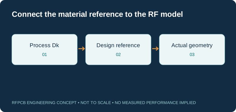
Separate process Dk from the design model
The process value and design reference serve different roles. Rogers lists a process Dk of 6.15 ± 0.15 and separately identifies design Dk 6.4. The datasheet notes that air gaps in clamped-stripline testing can influence the reported value. Retain the manufacturer method and conditions when documenting the reference; do not label the process tolerance as a finished-circuit tuning guarantee.
For a transmission line or resonator, identify the dielectric value used by the chosen model and how it relates to the geometry. An effective permittivity also reflects field distribution, including the air above an exposed microstrip. Keep it separate from both manufacturer entries. If an existing simulation library uses a different reference, resolve that discrepancy before changing artwork. Store the model version and material assumptions with the released stackup so later fabrication proposals can be checked against the design basis.
Use higher permittivity where electrical dimensions matter
RO4360G2 can be considered when distributed RF features occupy valuable space. The useful question is which part of the design would benefit from a different electrical scale. Identify resonators, matching sections or feeds whose dimensions follow the propagation environment, and distinguish them from component footprints and mechanical interfaces that remain fixed.
A smaller resonant feature does not necessarily produce a smaller complete board or improve its RF performance. The available trace width, coupling gap, connector launch and manufacturing tolerances may change with the revised construction. Model the affected structures together rather than scaling every dimension by a single ratio. For an antenna, include the surroundings and mounting arrangement in the evaluation. For a filter, include coupling and terminations. The decision should explain what space is saved, which sensitivities change and what evidence will support the final dimensions.
Interpret the resonance explorer as a sensitivity tool
The calculator relates resonance to electrical length and effective permittivity in a simplified model. It is useful for exploring whether a small change in modeled permittivity or path length could consume the available tuning margin. Enter effective values appropriate to the modeled structure, and use the same assumptions for the reference and changed scenarios.
The result is not a filter synthesis, antenna simulation or prediction of manufacturing yield. It omits fringing, coupling, dispersion, temperature-dependent behavior and changes in the surrounding assembly. A calculated shift therefore identifies a question for further analysis rather than an approved tolerance. Review the actual geometry with a suitable electromagnetic model and a representative prototype. When several parameters change together, record the full scenario so the result is not later misread as a material-only effect or a measured frequency shift.
Review temperature behavior over the product requirement
A room-temperature reference cannot establish response over the complete operating environment. Describe the temperature range, warm-up behavior, duty cycle and required RF limits for the product. Identify whether the sensitive circuit is exposed to ambient variation, nearby device heating or both. Those conditions determine the useful scope of simulation and measurement.
Avoid substituting a generic “stable Dk” statement for an application-specific review. The material model, thermal expansion, conductor dimensions and components can all contribute to a response change. Where a narrowband circuit has little tuning margin, examine performance at relevant conditions and after any required environmental exposure. Use repeatable mounting and measurement procedures so differences can be interpreted. Keep the thermal and RF records connected to the same board revision and stackup. This supports a later design change without assuming that a single laminate parameter describes the whole assembly.
Review the fabrication guide for this exact grade
Rogers provides a dedicated RO4360G2 fabrication guide. It discusses drilling, preparation and bonding in the context of this material, including the influence of bonding layers on multilayer hole preparation. The broad description of FR-4-like processing does not remove the need for a construction-specific manufacturing review.
Supply the finished hole schedule, stackup and critical dimensions before freezing small RF features. Ask the fabricator to identify the proposed process and inspection scope for the actual board. Agree which dimensions control the electrical response and which can use ordinary drawing tolerances. If an edge launch, cavity or plated feature is sensitive, make its geometry explicit. A useful DFM response resolves the proposed build and any requested changes; it does not promise that every thickness, layer count and feature combination has already been qualified.
Specify bonding layers and reference planes together
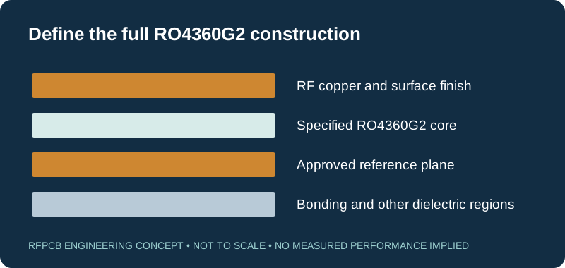
The manufacturer product page identifies combinations with RO4400-series prepregs and lower-Dk RO4000 laminates. Treat that as a starting point for a reviewed multilayer proposal. Specify the bonding product, pressed thickness and copper arrangement instead of leaving the entire build under one RO4360G2 label.
Use the multilayer RF guide to document reference planes and layer transitions. A field crossing into another dielectric region requires the appropriate model for that region. If cost or routing density motivates a hybrid construction, identify which layers contain the higher-permittivity core and why. Review symmetry, interconnects and assembly requirements with the proposed stackup. Keep the approved RF path visible when purchasing evaluates another bonding or support-layer option.
Model conductor loss and heat transfer explicitly
The listed Df and thermal conductivity are material references. A complete amplifier or feed network also depends on conductor geometry, foil texture, finish, plated features and attachment. Allocate path loss by the structures actually present, using comparable data at the operating band. The RF loss guide can help identify which contribution needs the most attention.
For thermal analysis, describe the dissipating devices and the heat route to the enclosure or sink. Include copper, vias, interfaces and cooling boundaries. Do not interpret laminate conductivity as a junction-temperature result or assume that a material change compensates for an undefined attachment interface. If a prototype compares two constructions, keep the power, mounting and ambient conditions consistent. Report RF and thermal results with their measurement boundaries so the evidence can support a real design decision.
Compare RO4360G2 and RO3006 as different constructions
A designer considering a nominal Dk around 6.15 may encounter both RO4360G2 and RO3006. The RO3006 and RO3010 guide describes the ceramic-filled PTFE path; RO4360G2 uses the thermoset construction discussed here. That difference warrants a new review of models, copper, geometry and fabrication assumptions even before comparing measured circuit results.
Prepare the comparison around the requirement driving the choice. If footprint is the concern, model the needed electrical response in each feasible stackup. If loss is the concern, compare equivalent path boundaries and account for conductor changes. If delivered cost is the concern, obtain quotations with matching quantity and test scope, then include qualification effort. Similar nominal Dk can make two candidates worth investigating; it does not authorize an undocumented substitution or guarantee unchanged artwork.
Define prototype acceptance and repeat-order controls
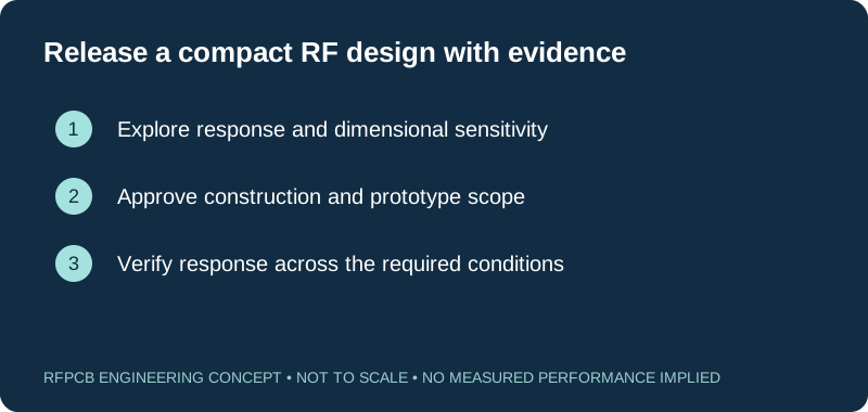
Choose an initial build that can verify the sensitive structures, then agree the operating band, limits and measurement setup. A straight impedance coupon may answer one manufacturing question while leaving filter response, antenna behavior or launch loss unresolved. State which evidence is required with the bare board and which belongs to the assembled product test.
Submit the files, material designation, quantity and review scope through the RFPCB quote form. Request confirmation of exact thickness, foil, bonding, sourcing and any proposed deviations. Retain the accepted construction and prototype record as the baseline for repeat orders. If material availability or process conditions later require a change, assess its effect before approving production. This guide supplies an engineering starting point; confirmed inventory, price, delivery and manufacturing acceptance belong in the project-specific proposal.
Prepare a reviewable engineering request
Check only the requirements you have actually documented. This list records readiness; it does not inspect your files or certify a design. Missing information is useful: identify it explicitly so the engineering review can resolve it before a production release.
These inputs are processed in your browser and are not submitted by this tool. The downloaded summary is a plain-text planning record. Use the secure quote form to send files; request an NDA first if your project requires one.
Manufacturing context
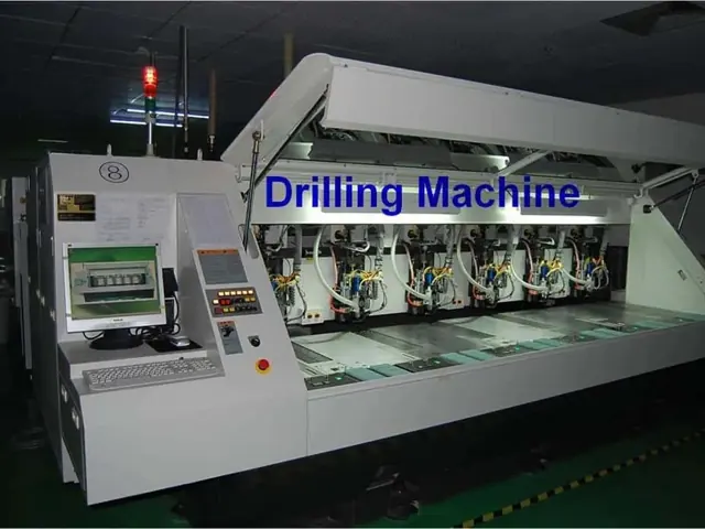
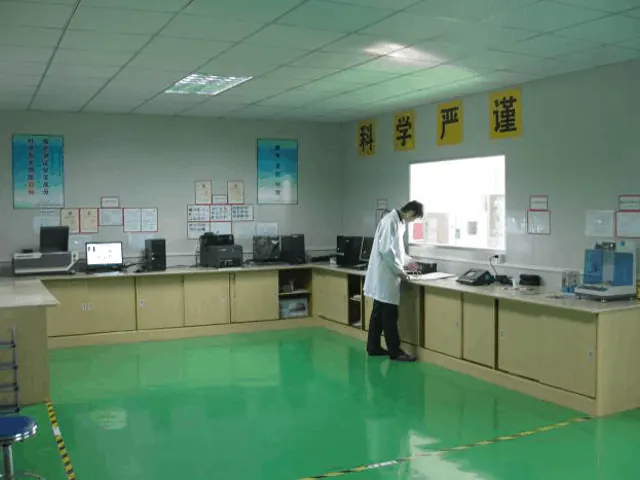
RFPCB and PCBSync share the manufacturing facility shown below. These process photographs illustrate the production environment; they are not evidence that a particular board, material grade or RF performance has been qualified. Request the documentation and inspection scope applicable to your project.

RO4360G2 PCB questions
Is RO4360G2 a ceramic-filled PTFE material?
No. Rogers identifies it as a glass-reinforced hydrocarbon/ceramic thermoset laminate. Ceramic filling alone does not identify the resin system. RO3006 belongs to a different, ceramic-filled PTFE family.
Should I use 6.15 or 6.4 for RO4360G2?
Rogers lists 6.15 ± 0.15 as process Dk and 6.4 as a design reference. Choose the model input appropriate to the structure and manufacturer guidance. Effective permittivity is another quantity determined by the transmission-line environment.
Can RO4360G2 replace RO3006 without changing the design?
That requires a documented comparison of the complete constructions and relevant RF evidence. Similar nominal process Dk does not establish matching loss, phase, temperature behavior, copper or processing. Preserve the baseline until the alternative is approved.
Does FR-4-like processing guarantee manufacturing availability?
No. The grade-specific fabrication guidance supports a process review, while actual material sourcing and build feasibility depend on thickness, foil, bonding, geometry, quantity and the proposed manufacturing scope. Obtain those commitments in the project quotation.
Continue your engineering review
Request an RO4360G2 stackup and manufacturing review
Share the complete fabrication package and the RF features that control performance. Ask for a reviewed construction, explicit sourcing assumptions and a prototype acceptance plan.
Sources and engineering scope
- Rogers RO4360G2 datasheet, revision 080322
- Rogers RO4360G2 product page and design-Dk reference
- Rogers RO4360G2 grade-specific fabrication guide
- Rogers RO3000 series datasheet: composite identity and method-specific electrical properties
- Rogers: circuit materials and high-frequency PCB losses
Manufacturer values apply to the identified grade, test method and construction. Engineering examples on this page are illustrative; they are not measured product results, inventory statements or certification claims. Manufacturer and product names belong to their respective owners. Keep the applicable datasheet revision with your approved manufacturing package.
Ready for a quotation?
Send your requirements for a material, stackup and manufacturing review. Price and schedule are confirmed for your project.