

Flexible RF interconnects · Construction review
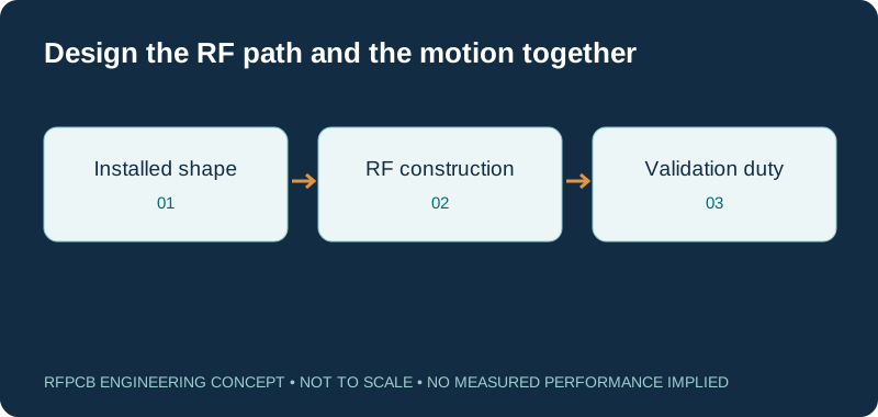
Flexible RF PCB design combines an RF transmission structure with a mechanical motion requirement. Define the installed shape, bending duty and measurement conditions alongside the dielectric and copper. A thin laminate alone does not establish a qualified flexible RF assembly.
A flexible RF PCB can be considered for shaped interconnects or moving RF paths when its exact material, copper, coverlay, grounding and transitions are reviewed together. Separate a one-time installation bend from repeated motion. Manufacturing feasibility and fatigue performance need construction-specific evidence; this page is not a blanket capability approval.
Match the flexible RF concept to its review requirement
| Design situation | Primary question | Information needed |
|---|---|---|
| Installed once | Will forming damage the circuit or alter RF response? | Final shape, forming method and inspection |
| Repeated motion | What duty must the complete circuit survive? | Bend cycle, radius, travel and environment |
| Low-loss interconnect | Which layers and materials carry the fields? | Clad, bonding, coverlay and copper definitions |
| Rigid-to-flex transition | How do signal and return cross the boundary? | Transition geometry, support and launch model |
| Connector attachment | How are mechanical forces transferred? | Stiffener, retention and assembly details |
| Production acceptance | What verifies mechanical and RF requirements? | Representative test article and agreed limits |
Flex bend geometry explorer
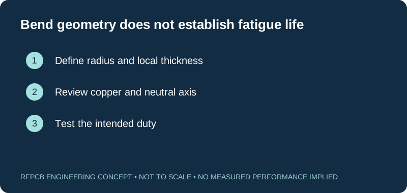
R/t is a geometric ratio. Ideal outer-surface strain = t/(2R), for a homogeneous symmetric section with its neutral axis halfway through the thickness. Enter the neutral-axis radius, not the inside radius. Real copper location, adhesives, coverlay and asymmetric stackups alter strain. This tool supplies no permitted bend radius, cycle count or fatigue approval.
Start with the movement, not just the outline
Show the flat circuit and its installed configuration in the manufacturing package. Identify the bend zone, supported regions, connector locations and nearby metal. State whether the circuit is bent during assembly, moved occasionally for service or cycled during normal operation. These are materially different requirements for engineering review.
For moving designs, provide travel, bend direction, speed, expected cycle count and environment. Explain whether curvature reverses or the circuit also experiences twisting. Supply dimensioned geometry and a defined motion profile to make the requirement repeatable.
Compare complete flex material systems
Pyralux TK is one candidate family for high-frequency flexible circuits. The current manufacturer overview describes a layered fluoropolymer and Kapton polyimide construction. That composition is distinct from an all-polyimide laminate; the word “flex” does not identify a single dielectric system.
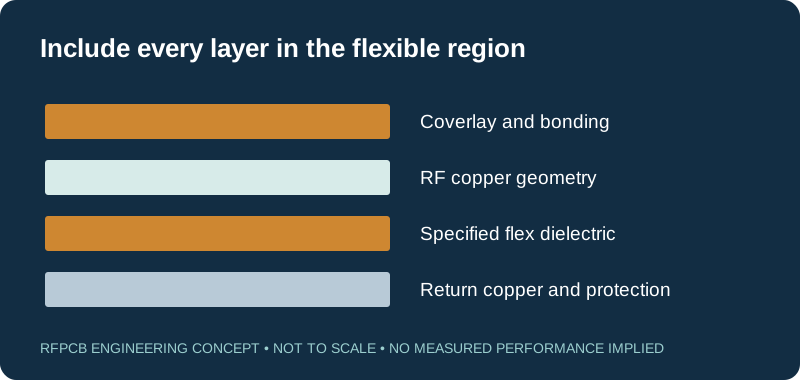
Specify the exact clad, bonding products, protective layers and copper, then obtain the applicable data and processing guidance. Review every dielectric close to the RF conductor. A low-loss core does not remove the need to model its coverlay or adhesive. Use the material selection guide to organize candidate builds without assuming that a material family is already approved for your product.
Understand what the bend calculator actually reports
The tool reports bend radius divided by local finished thickness, R/t. It also estimates outside-surface strain as t/(2R), assuming a symmetric construction whose neutral axis is at mid-thickness. Here R is the radius of that assumed neutral axis. If a drawing gives an inside radius, convert it consistently before using the estimate.
Real copper and polymer layers have different stiffnesses, and an asymmetric construction can move the neutral axis. Local plating, coverlay edges and stiffeners complicate the picture further. The result is a geometry comparison, not a fatigue model, approved minimum radius or pass/fail judgment. It does not determine allowable copper strain or predict service life.
Preserve a defined RF return through the bend
An RF trace needs a reviewed return path along the flexible region and across both ends. Decide where the return current travels and how that path connects to the rigid board, connector or shield. Include any ground pattern in the electrical model and the mechanical review; changing the pattern can change both stiffness and RF behavior.
Nearby enclosure metal may become part of the installed electromagnetic environment. Model the spacing that the assembly actually holds, including its permitted movement. The controlled-impedance guide helps define the transmission structure and acceptance scope, but a straight flat coupon cannot by itself qualify every folded installation.
Review conductor thickness and foil with the motion
State the copper type and thickness in the bend region, including any plated additions. Keep conductor routing, local transitions and mechanical supports visible in the same review. A stiffener edge or connector termination should not become an accidental hinge because the motion drawing omitted where the circuit is restrained.
Avoid choosing a universal bend multiplier from an unrelated example. Ask for a proposal tied to the specific layer count, copper distribution and duty. Where mechanical durability is critical, define the representative sample and failure criteria before testing. Record the actual fixture and motion so a later material or artwork change can be compared against the same requirement.
Budget loss for the actual length and assembled shape
Flexibility may allow a more direct interconnect, but the proposed route can also be longer or have narrower conductors than a rigid alternative. Compare the full RF path, including both end transitions and any connectors. Keep the same frequency range and measurement boundaries when comparing mechanical concepts.
Use the RF PCB loss guide to allocate line attenuation and discrete contributions. Evaluate relevant installed shapes rather than relying entirely on flat-circuit data. When a moving circuit must maintain phase as well as amplitude, specify both requirements and identify the motion states or continuous monitoring needed to capture the behavior that matters.
Design the rigid-to-flex transition as a separate region
The transition combines mechanical restraint, changing dielectric surroundings and often a change in RF geometry. Show the signal, ground connections, copper terminations and bonding boundaries together. Define how the flexible section is supported during assembly and in the final product, including strain relief and connector retention.
Keep joints and component placements consistent with the intended motion zones. Review assembly access before freezing the outline; a mechanically attractive folded shape may make inspection or rework difficult. The RF PCB assembly guide can help define the delivered article, from an unpopulated circuit to a connectorized assembly with a specified inspection and test plan.
Validate mechanical duty and RF acceptance together
An open-circuit check alone does not answer every RF reliability question. Depending on the project, acceptance may require continuity, visual inspection, insertion loss, return loss and phase measurements before, during or after defined mechanical exposure. Specify the fixture, environment, motion and measurement states so the result can be reproduced.
Keep the test article representative of the released copper, coverlay, stiffeners and attachment method. If a simplified coupon is used, document what it represents and what still needs verification in the product. Material datasheet tests can inform candidate selection; they do not automatically establish the cycle life or RF stability of your finished design.
Make the flex quotation comparable and reviewable
Provide the flat artwork, installed drawing, stackup, bend duty, quantities and assembly scope through the project quote form. Ask engineering to identify unresolved construction or process questions explicitly. RFPCB and PCBSync share a manufacturing facility, but that relationship does not establish approval for every flexible material and motion requirement.
Separate fabrication, assembly, fixtures and qualification in the budget. Use the RF PCB cost planner for confirmed inputs, while treating its rectangular panel model cautiously for irregular flex outlines. A comparable proposal should state the supplied configuration, testing obligations and material assumptions rather than relying on a generic per-piece flex price.
Prepare a reviewable engineering request
Check only the requirements you have actually documented. This list records readiness; it does not inspect your files or certify a design. Missing information is useful: identify it explicitly so the engineering review can resolve it before a production release.
These inputs are processed in your browser and are not submitted by this tool. The downloaded summary is a plain-text planning record. Use the secure quote form to send files; request an NDA first if your project requires one.
Manufacturing context
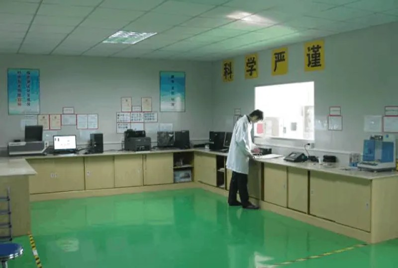
RFPCB and PCBSync share the manufacturing facility shown below. These process photographs illustrate the production environment; they are not evidence that a particular board, material grade or RF performance has been qualified. Request the documentation and inspection scope applicable to your project.


Flexible RF PCB FAQs
Can any thin RF laminate be used as a flexible PCB?
No. Thickness alone does not establish forming suitability, manufacturing compatibility or repeated-bend reliability. Review the material system, copper, layer arrangement, supported regions and required duty together before approving the construction.
What bend radius does the calculator approve?
None. It reports R/t and an ideal outside-surface strain estimate for a symmetric neutral-axis assumption. A qualified minimum bend radius depends on the complete construction and intended duty, with appropriate mechanical evidence.
Will bending change the RF response?
It can change geometry and proximity to surrounding metal, and mechanical damage can affect the conductor. Define the installed and moving configurations that matter, then model or measure the relevant response under those conditions.
Does using Pyralux TK guarantee a qualified RF flex product?
No. The material is a candidate within a complete construction. Exact product data, processing, copper, protective layers, transitions and application testing must support the specific design. Supplier literature is not a finished-board approval.
Continue your engineering review
Submit a flexible RF construction for review
Include the installed shape, motion profile, proposed materials and RF acceptance limits. Request an explicit feasibility and validation discussion for the exact construction.
Sources and engineering scope
Manufacturer values apply to the identified grade, test method and construction. Engineering examples on this page are illustrative; they are not measured product results, inventory statements or certification claims. Manufacturer and product names belong to their respective owners. Keep the applicable datasheet revision with your approved manufacturing package.
Ready for a quotation?
Send your requirements for a material, stackup and manufacturing review. Price and schedule are confirmed for your project.