Understanding Controlled impedance
Controlled impedance is a critical concept in the world of electrical engineering and Signal Integrity. It refers to the precise management of the impedance values in transmission lines, printed circuit boards (PCBs), and interconnects to ensure proper signal propagation and minimize unwanted reflections. In today’s high-speed digital systems, where signals travel at incredibly fast speeds and high frequencies, controlling impedance has become more important than ever.
What is Impedance?
To understand controlled impedance, we first need to grasp the concept of impedance itself. Impedance is a measure of the opposition that a circuit presents to the flow of alternating current (AC) at a given frequency. It is a complex quantity that combines resistance and reactance, and is measured in ohms (Ω).
In a transmission line, impedance is determined by the physical characteristics of the conductor and the dielectric material surrounding it. These characteristics include the conductor’s width, thickness, and spacing, as well as the dielectric constant and thickness of the insulating material.
Why Control Impedance?
Controlling impedance is essential for several reasons:
- Signal Integrity: When a signal travels along a transmission line, any mismatch in impedance between the source, the line, and the load can cause reflections. These reflections can lead to signal distortion, overshoot, undershoot, and ringing, which can compromise the integrity of the signal and cause errors in data transmission.
- Power Transfer: Maximum power transfer occurs when the impedance of the source matches the impedance of the load. By controlling impedance, we can ensure efficient power transfer and minimize power loss.
- Electromagnetic Compatibility (EMC): Uncontrolled impedance can lead to electromagnetic interference (EMI) issues. By maintaining a consistent impedance throughout the system, we can minimize EMI and ensure compliance with EMC regulations.
Techniques for Controlling Impedance
There are several techniques used to control impedance in PCBs and interconnects. Let’s explore some of the most common methods:
Trace Width and Spacing
One of the primary ways to control impedance is by adjusting the width and spacing of the traces on a PCB. The characteristic impedance of a trace is determined by its geometry and the properties of the surrounding dielectric material.
For a given dielectric thickness and constant, increasing the trace width decreases the characteristic impedance, while decreasing the trace width increases the impedance. Similarly, increasing the spacing between traces increases the impedance, while decreasing the spacing lowers the impedance.
PCB Designers use impedance calculators and simulation tools to determine the appropriate trace width and spacing for a desired characteristic impedance.
Dielectric Material Selection
The choice of dielectric material also plays a crucial role in controlling impedance. The dielectric constant (Dk) of the material determines how much the electric field is concentrated between the conductor and the ground plane.
Materials with a higher Dk, such as FR-4, concentrate the electric field more, resulting in lower characteristic impedance. On the other hand, materials with a lower Dk, such as Rogers RO4003C, spread the electric field more, leading to higher characteristic impedance.
| Material | Dielectric Constant (Dk) | Typical Applications |
|---|---|---|
| FR-4 | 4.2 – 4.5 | General-purpose PCBs, low-cost applications |
| Rogers RO4003C | 3.38 | High-frequency PCBs, RF and microwave applications |
| Isola IS410 | 3.96 | High-speed digital PCBs, automotive applications |
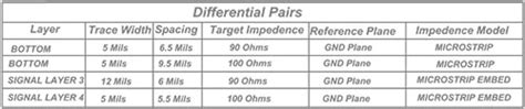
Differential Pairs
In high-speed digital systems, differential signaling is often used to improve signal integrity and reduce EMI. Differential pairs are two conductors that carry equal and opposite signals, with the signal being the difference between the two voltages.
To control the impedance of differential pairs, designers must consider the trace width, spacing, and the coupling between the two conductors. The differential impedance is determined by the odd-mode impedance, which is the impedance seen by the differential signal.
Proper spacing and coupling between the differential pairs help to maintain a consistent differential impedance and minimize crosstalk between adjacent pairs.
Impedance Matching
Impedance matching is the practice of designing the impedance of the source, transmission line, and load to be equal, thereby minimizing reflections and ensuring maximum power transfer.
In PCB design, impedance matching is often achieved through the use of termination resistors. These resistors are placed at the end of the transmission line, near the receiver, and their value is chosen to match the characteristic impedance of the line.
Common termination techniques include:
- Series termination: A resistor is placed in series with the source, matching the impedance of the line.
- Parallel termination: A resistor is placed in parallel with the load, matching the impedance of the line.
- Thevenin termination: A combination of series and parallel resistors is used to match the impedance of the line.

Measuring and Verifying Controlled Impedance
To ensure that the controlled impedance targets are met, it is essential to measure and verify the impedance of the manufactured PCB. There are several methods for measuring impedance, including:
Time Domain Reflectometry (TDR)
TDR is a technique that measures the impedance of a transmission line by sending a fast-rising pulse down the line and measuring the reflections that occur when the pulse encounters impedance discontinuities.
A TDR instrument displays the impedance profile of the line as a function of time, allowing engineers to identify impedance mismatches and locate their positions along the line.
Impedance Test Coupons
Impedance test coupons are small PCB sections that are designed to mimic the impedance of the actual traces on the board. These coupons are typically placed along the edge of the PCB Panel and are used to verify the impedance of the manufactured board.
The coupons are measured using a specialized impedance testing machine, which applies a high-frequency signal to the coupon and measures the resulting impedance. By comparing the measured impedance to the target value, engineers can determine whether the board meets the specified impedance requirements.

Frequently Asked Questions (FAQ)
- What is the difference between characteristic impedance and differential impedance?
- Characteristic impedance refers to the impedance of a single transmission line, considering the trace geometry and dielectric properties. Differential impedance, on the other hand, is the impedance seen by a differential signal traveling along a pair of coupled traces.
- How does the dielectric constant affect characteristic impedance?
- The dielectric constant (Dk) of the insulating material determines how much the electric field is concentrated between the conductor and the ground plane. A higher Dk results in a lower characteristic impedance, while a lower Dk leads to a higher characteristic impedance.
- What is the purpose of impedance matching?
- Impedance matching is used to minimize reflections and ensure maximum power transfer by designing the impedance of the source, transmission line, and load to be equal. This is typically achieved through the use of termination resistors.
- Why is it important to control impedance in high-speed digital systems?
- In high-speed digital systems, controlling impedance is crucial for maintaining signal integrity, minimizing reflections, and reducing electromagnetic interference (EMI). Uncontrolled impedance can lead to signal distortion, data errors, and EMC compliance issues.
- What are the common methods for measuring and verifying controlled impedance?
- The two most common methods for measuring and verifying controlled impedance are Time Domain Reflectometry (TDR) and impedance test coupons. TDR measures the impedance profile of a transmission line by sending a fast-rising pulse and analyzing the reflections, while impedance test coupons are small PCB sections designed to mimic the impedance of the actual traces and are measured using a specialized impedance testing machine.

Conclusion
Controlled impedance is a vital aspect of modern PCB design and signal integrity. By carefully managing the impedance of transmission lines, designers can ensure proper signal propagation, minimize reflections, and reduce EMI. This is achieved through techniques such as adjusting trace geometry, selecting appropriate dielectric materials, and implementing impedance matching.
As digital systems continue to push the boundaries of speed and performance, the importance of controlled impedance will only continue to grow. By understanding the principles and techniques involved in controlling impedance, engineers can design more reliable, efficient, and robust electronic systems.
Leave a Reply