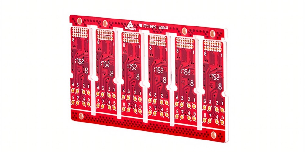
Rogers Corporation is a leading manufacturer of high frequency circuit substrate materials used in a variety of wireless, aerospace, defense and communications applications. Their Rogers RO4000® series high frequency circuit materials have excellent dielectric properties, low loss, and stable electrical performance across a wide frequency range.
Key Properties of Rogers RF Materials
Some of the key properties that make Rogers RF materials suitable for high frequency applications include:
- Low dielectric constant (Dk) – Typically between 3.0-3.5, which helps minimize signal loss and propagation delays.
- Low dissipation factor (Df) – Values such as 0.009 at 10 GHz ensure low signal loss and insertion loss.
- Thermal conductivity – Up to 0.67 W/m/K provides effective heat dissipation.
- Controlled dielectric thickness – Allows tight impedance control.
- Good dimensional stability – Low Z-axis expansion preserves circuit performance.
- UL 94V-0 flame rating – Suitable for commercial and defense applications.
- RoHS compliant – Meets environmental regulations on hazardous substances.
Typical Applications
Some example applications where Rogers RF materials are commonly used:
Wireless Communications
- 5G antennas and arrays
- Microwave point-to-point radios
- Satellite communications
- Radar systems
Aerospace and Defense
- Phased array antennas
- AESA radars
- Missile guidance systems
- Electronic warfare systems
High Speed Digital
- High speed data links
- Optical networking
- Test and measurement equipment
Rogers RF Materials Comparison Table
| Material | Dielectric Constant | Loss Tangent | Frequency Range | Key Features |
|---|---|---|---|---|
| RO3003TM | 3.00 | 0.0013 | Up to 6 GHz | UL 94 V-0, low cost, entry level |
| RO3010TM | 10.2 | 0.0035 | Up to 10 GHz | Higher frequency, low loss |
| RO4003CTM | 3.38 | 0.0027 | Up to 6 GHz | High thermal cond., tight εr control |
| RO4350BTM | 3.48 | 0.0037 | Up to 12 GHz | Low Df, high thermal cond.,doming |
Frequently Asked Questions

Q: What is the difference between Rogers RO4003C and RO4350B materials?
A: RO4003C has a dielectric constant of 3.38 while RO4350B is 3.48. RO4350B has a lower loss tangent (0.0037 vs 0.0027) and higher thermal conductivity, making it suitable for higher power and frequency applications. RO4003C offers tighter dielectric constant control.
Q: Can Rogers RF materials be used for mmWave frequencies?
A: Yes, Rogers 3000 and 4000 series materials like RT/duroid® 5880, 5870, 6002, 6202, 3003 can be used up to mmWave bands like 60-100 GHz for 5G applications. The ultra-low loss and stable dielectric properties extend to extremely high frequencies.
Q: What is the difference between ceramic filled and glass microfiber filled RF laminates?
A: Ceramic filled materials like RO4003C have higher thermal conductivity allowing better heat dissipation. Glass microfiber filled laminates like RO3003 have more isotropic properties and lower Z-axis CTE for improved dimensional stability.
Q: Can Rogers RF materials be machined using standard PCB fabrication methods?
A: Yes, Rogers RF laminates are fully compatible with standard PCB processes like photolithography, etching, drilling, routing, and deposition. They can also be laser machined or photopatterned.
Q: What are some guidelines for designing with Rogers RF materials?
A: Use adequate ground planes, proper transmission line dimensions, controlled impedance, mitred bends, no acid traps, smooth copper and minimize unused areas of copper to avoid losses and inconsistencies. Follow Rogers design guidelines for best results.

Leave a Reply