Introduction to Rigid-Flex PCBs
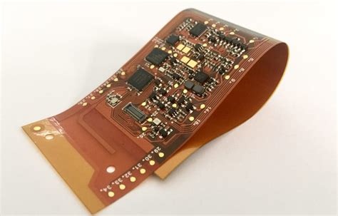
Rigid-flex PCBs are a unique type of printed circuit board that combines the benefits of both rigid and flexible circuits. These hybrid boards consist of rigid PCB sections connected by flexible interconnects, enabling 3D configurations and dynamic flexing not possible with traditional rigid boards. Rigid-flex technology offers numerous advantages, including:
- Reduced size and weight
- Increased reliability
- Improved signal integrity
- Enhanced design flexibility
- Streamlined assembly
The combination of rigid and flex circuits into a single board allows for compact, high-density packaging of electronic components. Rigid-flex PCBs can fold, bend, and twist to fit into tight, unconventional spaces while providing robust mechanical and electrical performance.
Advantages of Rigid-Flex PCB Design
Space Savings and Miniaturization
One of the primary benefits of rigid-flex PCBs is their ability to significantly reduce the size and weight of electronic devices. By eliminating bulky connectors and cables between rigid boards, rigid-flex designs enable tighter packaging and higher component density. The flexible interconnects can be folded and shaped to optimize space utilization, allowing for miniaturization of the overall device.
Space savings achieved through rigid-flex PCB design:
| Application | Space Savings |
|---|---|
| Smartphones | 30-50% |
| Wearables | 40-60% |
| Medical devices | 25-40% |
| Aerospace systems | 20-35% |
Enhanced Reliability and Durability
Rigid-flex PCBs offer superior reliability compared to traditional multi-board assemblies with connectors and cables. The flexible interconnects provide a continuous, seamless connection between the rigid sections, eliminating potential points of failure such as solder joints and contact interfaces. This inherent reliability makes rigid-flex PCBs ideal for applications subjected to vibration, shock, and repeated flexing.
Flexible circuit materials, such as polyimide, exhibit excellent mechanical and thermal stability, ensuring long-term durability. The ability to withstand multiple flex cycles without degradation or loss of electrical performance is a key advantage of rigid-flex designs.
Improved Signal Integrity
The integrated nature of rigid-flex PCBs brings signal integrity benefits. By reducing the number of interconnects and minimizing the distance signals must travel, rigid-flex designs can minimize signal loss, crosstalk, and electromagnetic interference (EMI). The shorter signal paths and Controlled impedance of the flexible interconnects contribute to cleaner, faster signal transmission.
Rigid-flex PCBs are particularly advantageous for high-speed applications, such as data communication and RF systems, where maintaining signal integrity is crucial. The ability to precisely control the impedance and routing of the flexible traces allows for optimized signal performance.
Design Flexibility and 3D Configurations
Rigid-flex PCBs offer unparalleled design flexibility, enabling the creation of complex, three-dimensional structures. The flexible interconnects can be shaped and folded to conform to unique device geometries and tight space constraints. This allows for innovative packaging solutions and the integration of multiple functions into a single, compact assembly.
Rigid-flex designs can accommodate various component types and sizes, including surface mount and Through-hole components, on both the rigid and flexible sections. The ability to place components on the flexible areas further enhances design flexibility and space utilization.
Streamlined Assembly and Cost Reduction
Rigid-flex PCBs streamline the assembly process by reducing the number of separate boards and interconnects required. Instead of assembling multiple rigid boards and connecting them with cables or connectors, a single rigid-flex PCB can integrate all the necessary circuitry into a unified structure. This simplifies assembly, reduces the risk of errors, and improves overall manufacturing efficiency.
The streamlined assembly process also translates into cost savings. By eliminating the need for separate connectors, cables, and additional assembly steps, rigid-flex designs can reduce material and labor costs. The improved reliability and durability of rigid-flex PCBs further contribute to long-term cost savings by minimizing the need for repairs or replacements.

Rigid-Flex PCB Manufacturing Process
Layer Stack-up and Materials
The manufacturing process for rigid-flex PCBs begins with the design and creation of the layer stack-up. The stack-up defines the arrangement of conductive layers, dielectric materials, and adhesives that make up the board. Careful selection of materials is crucial to ensure the desired electrical, mechanical, and thermal properties.
Typical materials used in rigid-flex PCB construction include:
- Flexible dielectric substrates (e.g., polyimide, polyester)
- Adhesives (e.g., acrylic, epoxy)
- Copper foil for conductive layers
- Rigid dielectric substrates (e.g., FR-4, high-Tg materials)
- Coverlay or solder mask for protection
The stack-up design must consider factors such as layer count, dielectric thickness, copper weight, and adhesive properties to achieve the required flexibility and performance.
Fabrication Steps
The rigid-flex PCB fabrication process involves several key steps:
-
Flexible layer preparation: The flexible dielectric substrate is cut to size, and copper foil is laminated onto one or both sides using adhesive. Photoresist is applied, and the desired circuit pattern is transferred onto the copper using photolithography.
-
Rigid layer preparation: The rigid dielectric layers are prepared similarly to traditional rigid PCBs. Copper foil is laminated onto the rigid substrate, and the circuit pattern is etched using photolithography and chemical etching.
-
Lamination: The flexible and rigid layers are aligned and laminated together using heat and pressure. Adhesive is used to bond the layers securely.
-
Drilling and plating: Through-holes and vias are drilled in the designated locations, and the holes are plated with copper to establish electrical connections between layers.
-
Patterning and etching: The outer layer circuit patterns are defined using photolithography, and the unwanted copper is removed through chemical etching.
-
Surface finish: A surface finish, such as ENIG (Electroless Nickel Immersion Gold) or OSP (Organic Solderability Preservative), is applied to the exposed copper pads to protect against oxidation and enhance solderability.
-
Coverlay and solder mask: A coverlay or solder mask is applied to the flexible and rigid areas, respectively, to provide insulation and protection for the circuits.
-
Cutting and routing: The rigid-flex PCB Panel is cut and routed to the desired shape and size using mechanical or laser cutting methods.
-
Testing and inspection: The fabricated rigid-flex PCBs undergo thorough testing and inspection to ensure they meet the specified electrical and mechanical requirements.
Design Considerations and Guidelines
Designing rigid-flex PCBs requires careful consideration of various factors to ensure manufacturability, reliability, and performance. Some key design guidelines include:
-
Bend radius: Ensure that the minimum bend radius of the flexible sections is adhered to, typically at least 10 times the total thickness of the flex layers, to prevent excessive stress and damage.
-
Copper balancing: Balance the copper distribution on both sides of the flexible layers to minimize stress and prevent warping during manufacturing and use.
-
Stiffeners: Use stiffeners strategically in the flexible areas to provide support and prevent excessive flexing in sensitive regions.
-
Trace routing: Route traces perpendicular to the bend direction to minimize stress on the conductors during flexing. Avoid routing traces near the edges of the flexible sections.
-
Strain relief: Incorporate strain relief features, such as curves or loops, in the flexible interconnects to distribute stress evenly and prevent damage during bending.
-
Panelization: Design the rigid-flex PCB layout to optimize panelization and minimize material waste during fabrication.
-
Component placement: Position components strategically on the rigid sections, considering the overall 3D configuration and potential flexing requirements.
-
Signal integrity: Follow signal integrity guidelines, such as controlled impedance routing and proper grounding, to ensure optimal performance, especially for high-speed signals.
-
Manufacturing tolerances: Consider manufacturing tolerances and limitations, such as minimum trace width and spacing, when designing the rigid-flex PCB layout.

Applications of Rigid-Flex PCBs
Rigid-flex PCBs find applications across various industries due to their unique capabilities and benefits. Some common applications include:
Consumer Electronics
Rigid-flex PCBs are widely used in consumer electronics, such as smartphones, tablets, and wearables. Their ability to enable compact, lightweight designs with improved reliability makes them ideal for these portable devices. Rigid-flex circuits can be folded and shaped to fit into the limited space available, allowing for sleek and ergonomic form factors.
Medical Devices
The medical industry relies on rigid-flex PCBs for various applications, including implantable devices, diagnostic equipment, and monitoring systems. Rigid-flex designs offer the necessary reliability, miniaturization, and biocompatibility required for medical devices. They can withstand the harsh sterilization processes and provide long-term performance in bodily fluids.
Automotive Electronics
Rigid-flex PCBs are increasingly used in automotive electronics, such as infotainment systems, driver assistance modules, and sensor assemblies. Their ability to withstand vibration, shock, and extreme temperatures makes them suitable for the demanding automotive environment. Rigid-flex designs enable the integration of multiple functions into compact, reliable modules, reducing weight and improving vehicle efficiency.
Aerospace and Defense
The aerospace and defense industries employ rigid-flex PCBs in applications such as avionics, satellite systems, and military equipment. Rigid-flex designs offer the ruggedness, reliability, and space savings necessary for these critical applications. They can withstand harsh environmental conditions, including extreme temperatures, vibration, and shock, ensuring reliable performance in demanding aerospace and defense scenarios.
Industrial Automation
Rigid-flex PCBs are used in industrial automation systems, including robotics, machine controls, and sensors. Their flexibility and durability enable the creation of compact, modular designs that can be easily integrated into automated equipment. Rigid-flex circuits can withstand the rigors of industrial environments, such as vibration, dust, and moisture, ensuring reliable operation and long service life.

Future Trends and Advancements
The rigid-flex PCB industry continues to evolve and innovate to meet the ever-increasing demands for miniaturization, performance, and reliability. Some future trends and advancements in rigid-flex technology include:
-
Advanced materials: The development of new flexible substrate materials, such as liquid crystal polymer (LCP) and polyethylene naphthalate (PEN), with improved electrical and mechanical properties will enable even more advanced rigid-flex designs.
-
High-density interconnect (HDI): The integration of HDI techniques, such as microvias and fine-pitch traces, into rigid-flex PCBs will allow for higher component density and miniaturization.
-
Embedded components: The embedding of active and passive components within the rigid-flex layers will further enhance space savings and enable the creation of highly integrated, multi-functional modules.
-
3D printing: The adoption of 3D printing technologies for rigid-flex PCB fabrication will enable faster prototyping, customization, and complex 3D structures.
-
5G and high-speed applications: As 5G networks and high-speed data transfer become more prevalent, rigid-flex PCBs will play a crucial role in enabling compact, high-performance devices that can handle the increased bandwidth and signal integrity requirements.
-
Wearables and IoT: The growth of wearable technology and the Internet of Things (IoT) will drive the demand for flexible, lightweight, and reliable rigid-flex PCBs that can be integrated into various devices and sensors.
-
Sustainable manufacturing: Efforts to develop eco-friendly materials and manufacturing processes for rigid-flex PCBs will gain momentum, promoting sustainability and reducing environmental impact.
Frequently Asked Questions (FAQ)
- Q: What is the typical cost comparison between rigid-flex PCBs and traditional rigid PCBs?
A: Rigid-flex PCBs generally have a higher cost compared to traditional rigid PCBs due to the specialized materials, manufacturing processes, and design complexity involved. However, the overall system cost can be lower with rigid-flex designs due to reduced assembly time, fewer components, and improved reliability.
- Q: Can rigid-flex PCBs be reworked or repaired?
A: Reworking or repairing rigid-flex PCBs can be challenging due to the intricate structure and bonding of the rigid and flexible layers. While minor repairs, such as replacing components on the rigid sections, may be possible, extensive rework or repair of the flexible interconnects is often impractical. It’s crucial to ensure proper design and manufacturing to minimize the need for rework.
- Q: How long do rigid-flex PCBs typically last in terms of flex cycles?
A: The lifespan of rigid-flex PCBs in terms of flex cycles depends on various factors, such as the materials used, the bend radius, and the environmental conditions. Properly designed and manufactured rigid-flex PCBs can withstand thousands to millions of flex cycles without significant degradation. The use of high-quality materials and adherence to design guidelines can maximize the flex life of rigid-flex PCBs.
- Q: Are there any limitations on the number of layers or the layer thickness in rigid-flex PCBs?
A: The number of layers and layer thickness in rigid-flex PCBs are limited by manufacturing capabilities and practical considerations. Rigid-flex PCBs can have multiple layers, typically ranging from 4 to 20 or more, depending on the complexity of the design. The thickness of individual layers is usually in the range of 0.05mm to 0.2mm, considering the flexibility requirements and overall board thickness.
- Q: How do I choose the right rigid-flex PCB manufacturer for my project?
A: Choosing the right rigid-flex PCB manufacturer is crucial for the success of your project. Consider factors such as the manufacturer’s experience and expertise in rigid-flex technology, their manufacturing capabilities and certifications, their ability to handle your specific design requirements, and their track record of quality and reliability. It’s also important to evaluate their communication, support, and delivery timelines to ensure a smooth collaboration.
Conclusion
Rigid-flex PCBs offer a powerful solution for designing compact, reliable, and high-performance electronic devices. By combining the benefits of rigid and flexible circuits, rigid-flex technology enables miniaturization, enhanced signal integrity, and improved overall system reliability. The unique capabilities of rigid-flex PCBs make them ideal for a wide range of applications, from consumer electronics and medical devices to automotive and aerospace systems.
As the demand for smaller, more complex, and more reliable electronic devices continues to grow, rigid-flex PCBs will play an increasingly important role in enabling innovative and efficient designs. With advancements in materials, manufacturing processes, and design techniques, the future of rigid-flex technology looks promising, offering exciting possibilities for the electronics industry.
When considering rigid-flex PCBs for your next project, it’s essential to partner with an experienced and reliable manufacturer who can provide the necessary expertise and support throughout the design and production process. By leveraging the capabilities of rigid-flex technology and following best design practices, you can create cutting-edge electronic devices that meet the evolving needs of today’s market.
Leave a Reply