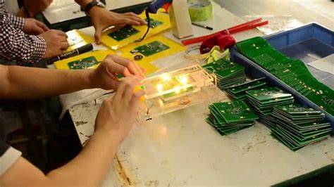
Introduction to PCB Testing
Printed Circuit Board (PCB) manufacturing is a complex process that involves several stages, from design and fabrication to assembly and testing. One of the critical steps in ensuring the quality and reliability of PCBs is electrical testing. Electrical testing is a process that verifies the electrical functionality and performance of a PCB, ensuring that it meets the specified requirements and is free from defects.
Why is PCB Testing Important?
PCB testing is essential for several reasons:
- Ensuring the quality and reliability of the PCB
- Detecting and identifying defects early in the manufacturing process
- Reducing the risk of product failures and recalls
- Improving customer satisfaction and brand reputation
- Compliance with industry standards and regulations
Types of PCB Testing
There are various types of PCB testing, each with its own purpose and methodology. Some of the common types of PCB testing include:
- In-Circuit Testing (ICT)
- Flying Probe Testing (FPT)
- Functional Testing
- Boundary Scan Testing (BST)
- Burn-In Testing
In-Circuit Testing (ICT)
In-Circuit Testing (ICT) is a type of electrical testing that verifies the functionality of individual components on a PCB. ICT is performed using a specialized test fixture that makes contact with the PCB through a bed of nails. The test fixture is designed to match the specific layout of the PCB, with each nail corresponding to a test point on the board.
How Does In-Circuit Testing Work?
- The PCB is placed on the test fixture, and the bed of nails makes contact with the test points on the board.
- The test system applies electrical signals to the test points and measures the response of the components.
- The measured values are compared to the expected values, and any deviations are identified as potential defects.
- The test system generates a report that includes the test results and any identified defects.
Advantages of In-Circuit Testing
- High test coverage, as each component is tested individually
- Fast and efficient, as multiple boards can be tested simultaneously
- Able to detect defects such as short circuits, open circuits, and incorrect component values
- Provides detailed diagnostic information for troubleshooting
Disadvantages of In-Circuit Testing
- Requires a specialized test fixture, which can be expensive and time-consuming to develop
- Limited to testing components that are accessible through test points
- May not detect defects in the interconnections between components

Flying Probe Testing (FPT)
Flying Probe Testing (FPT) is a type of electrical testing that uses movable probes to test the functionality of a PCB. Unlike ICT, FPT does not require a specialized test fixture and can test both components and interconnections.
How Does Flying Probe Testing Work?
- The PCB is placed on a test platform, and the movable probes are positioned above the board.
- The test system moves the probes to the desired test points on the PCB and makes contact with the board.
- The test system applies electrical signals to the test points and measures the response of the components and interconnections.
- The measured values are compared to the expected values, and any deviations are identified as potential defects.
- The test system generates a report that includes the test results and any identified defects.
Advantages of Flying Probe Testing
- Flexible and adaptable, as it can test a wide range of PCB designs without requiring a specialized test fixture
- Able to test both components and interconnections
- Provides high test coverage and detailed diagnostic information
- Ideal for low-volume production runs or prototype testing
Disadvantages of Flying Probe Testing
- Slower than ICT, as each test point must be probed individually
- More expensive than ICT for high-volume production runs
- Requires accurate and up-to-date CAD data for test program generation

Functional Testing
Functional testing is a type of electrical testing that verifies the overall functionality and performance of a PCB. Unlike ICT and FPT, which test individual components and interconnections, functional testing evaluates the PCB as a complete system.
How Does Functional Testing Work?
- The PCB is connected to a test system that simulates the intended operating environment.
- The test system applies input signals to the PCB and measures the output response.
- The measured output is compared to the expected output, and any deviations are identified as potential defects.
- The test system may also perform stress testing, subjecting the PCB to extreme conditions to evaluate its reliability and durability.
- The test system generates a report that includes the test results and any identified defects.
Advantages of Functional Testing
- Verifies the overall functionality and performance of the PCB
- Ensures that the PCB meets the specified requirements and is free from defects
- Can detect defects that may not be identified by ICT or FPT, such as timing issues or signal integrity problems
- Provides a high level of confidence in the quality and reliability of the PCB
Disadvantages of Functional Testing
- Requires the development of complex test programs and fixtures
- May not provide detailed diagnostic information for troubleshooting
- Can be time-consuming and expensive, especially for high-complexity PCBs

Boundary Scan Testing (BST)
Boundary Scan Testing (BST) is a type of electrical testing that verifies the functionality of digital components on a PCB. BST is based on the IEEE 1149.1 standard, which defines a method for accessing and testing the boundary pins of digital components.
How Does Boundary Scan Testing Work?
- The PCB is designed with boundary scan compliant components, which include a boundary scan cell for each pin.
- The test system connects to the PCB through a boundary scan interface, typically a JTAG (Joint Test Action Group) port.
- The test system sends instructions to the boundary scan cells, which can force or capture the state of the pins.
- The test system compares the captured state to the expected state and identifies any deviations as potential defects.
- The test system generates a report that includes the test results and any identified defects.
Advantages of Boundary Scan Testing
- Provides access to pins that may not be accessible through physical probing
- Able to test complex digital components, such as FPGAs and microprocessors
- Offers high test coverage and detailed diagnostic information
- Can be used for programming and debugging of firmware
Disadvantages of Boundary Scan Testing
- Limited to testing digital components that are boundary scan compliant
- Requires the design of the PCB to include boundary scan architecture
- May not detect defects in analog components or interconnections
Burn-In Testing
Burn-In Testing is a type of electrical testing that subjects a PCB to elevated temperatures and voltages for an extended period to identify potential early-life failures. Burn-In Testing is typically performed on a sample of PCBs from a production run to assess the reliability and durability of the boards.
How Does Burn-In Testing Work?
- The PCBs are placed in a temperature-controlled chamber and connected to a test system.
- The test system applies elevated temperatures and voltages to the PCBs, typically above the normal operating conditions.
- The PCBs are operated in this environment for an extended period, typically several hours or days.
- The test system monitors the performance of the PCBs and identifies any failures or degradation in functionality.
- The test results are used to calculate the expected failure rate and reliability of the PCBs.
Advantages of Burn-In Testing
- Identifies potential early-life failures, improving the reliability and durability of the PCBs
- Provides a measure of the expected failure rate and reliability of the PCBs
- Can detect defects that may not be identified by other testing methods, such as temperature-dependent failures
Disadvantages of Burn-In Testing
- Requires specialized equipment and facilities, such as temperature-controlled chambers
- Can be time-consuming and expensive, as it requires extended testing periods
- May not be practical for high-volume production runs or low-cost PCBs
PCB Testing Strategies
Developing an effective PCB testing strategy is essential for ensuring the quality and reliability of PCBs while minimizing testing costs and time. Some key considerations for developing a PCB testing strategy include:
- Identifying the critical components and functions of the PCB
- Determining the appropriate testing methods for each component and function
- Establishing testing requirements and acceptance criteria based on industry standards and customer specifications
- Balancing testing coverage and cost, considering factors such as production volume, product complexity, and target market
- Implementing a quality management system to monitor and continually improve the testing process
| Testing Method | Advantages | Disadvantages |
|---|---|---|
| In-Circuit Testing (ICT) | High test coverage, fast and efficient, detailed diagnostics | Requires specialized test fixture, limited to accessible components |
| Flying Probe Testing (FPT) | Flexible and adaptable, tests components and interconnections, high coverage | Slower than ICT, more expensive for high-volume production |
| Functional Testing | Verifies overall functionality and performance, detects system-level defects | Requires complex test programs and fixtures, may not provide detailed diagnostics |
| Boundary Scan Testing (BST) | Access to non-accessible pins, tests complex digital components, high coverage | Limited to boundary scan compliant components, requires boundary scan architecture |
| Burn-In Testing | Identifies early-life failures, provides reliability metrics | Requires specialized equipment, time-consuming and expensive |
Frequently Asked Questions (FAQ)
1. What is the difference between ICT and FPT?
In-Circuit Testing (ICT) uses a specialized test fixture with a bed of nails to test individual components on a PCB, while Flying Probe Testing (FPT) uses movable probes to test both components and interconnections without requiring a specialized fixture.
2. Can functional testing replace ICT or FPT?
Functional testing verifies the overall functionality and performance of a PCB but may not provide the same level of diagnostic information as ICT or FPT. A comprehensive testing strategy often includes a combination of different testing methods to ensure the highest quality and reliability.
3. Is boundary scan testing applicable to all PCBs?
Boundary scan testing is limited to PCBs that include boundary scan compliant components and have been designed with the necessary boundary scan architecture. Not all PCBs are suitable for boundary scan testing.
4. How long does burn-in testing typically take?
The duration of burn-in testing can vary depending on the specific requirements and target reliability of the PCB. Typical burn-in testing periods range from several hours to several days, with the PCBs being subjected to elevated temperatures and voltages throughout the testing process.
5. How can I determine the most cost-effective testing strategy for my PCBs?
Determining the most cost-effective testing strategy requires considering factors such as the complexity of the PCB, the production volume, the target market, and the required quality and reliability levels. Working with experienced PCB testing providers and conducting a thorough analysis of testing requirements and costs can help identify the optimal testing strategy for a given PCB design and production scenario.
Conclusion
Electrical testing is a critical step in the PCB manufacturing process, ensuring that the boards meet the specified requirements and are free from defects. There are several types of electrical testing, each with its own advantages and disadvantages, and the choice of testing method depends on the specific requirements and characteristics of the PCB.
Developing an effective PCB testing strategy requires careful consideration of the critical components and functions of the PCB, the appropriate testing methods for each component and function, and the balance between testing coverage and cost. By implementing a comprehensive and well-designed testing strategy, PCB manufacturers can ensure the highest quality and reliability of their products while minimizing testing costs and time.
As PCB technology continues to evolve, with increasing complexity and miniaturization, the importance of effective electrical testing will only continue to grow. By staying up-to-date with the latest testing methods and best practices, PCB manufacturers can stay competitive and meet the ever-increasing demands of the electronics industry.
Leave a Reply