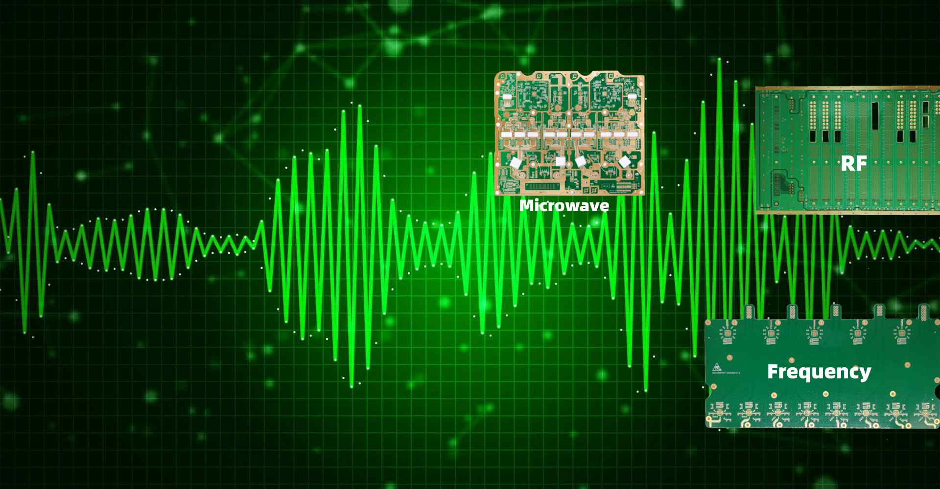
When designing radio frequency (RF) printed circuit boards (PCBs), choosing the right substrate material is crucial for optimal performance. The substrate plays a key role in determining parameters like dielectric constant, loss tangent, thermal conductivity and coefficient of thermal expansion. This article provides an overview of the commonly used RF PCB materials and guidelines for substrate selection.
FR-4
Overview
FR-4 is the most common and cost-effective substrate for RF PCBs. It is a glass reinforced epoxy laminate material.
Properties
- Dielectric constant: 4.2-4.8
- Loss tangent: 0.02
- Thermal conductivity: 0.25 W/mK
- Z-axis expansion: 60-100 ppm/°C
Applications
Well suited for low frequency applications below 3 GHz like ISM bands and RFID. Used in cost-sensitive consumer electronics.
High Frequency Laminates

PTFE Based Laminates
Polytetrafluoroethylene (PTFE) based substrates like Rogers RO4000 series offer superior high frequency performance.
Properties
- Dielectric constant: 3.38
- Loss tangent: 0.0027
- Thermal conductivity: 0.71 W/mK
Applications
Ideal for antennas, radar and satellite communication applications above 10 GHz. Rogers RO4350 is commonly used in 5G mmWave antennas.
Ceramic Filled PTFE Laminates
Ceramic fillers like silica are added to PTFE to improve thermal conductivity and dimensional stability.
Properties
- Dielectric constant: 3-10
- Loss tangent: 0.0015-0.0025
- Thermal conductivity: 1-3 W/mK
Applications
Used in automotive radar PCBs that require improved heat dissipation. Rogers RO4835 is a common ceramic filled PTFE material.
High Frequency Ceramic Substrates
Ceramic substrates have the highest performance characteristics but also relatively high cost.
Alumina Substrates
Alumina substrates provide high dielectric constant along with low loss.
Properties
- Dielectric constant: 9.8
- Loss tangent: 0.0002
- Thermal conductivity: 24 W/mK
Applications
Ideal for ultra high frequency applications over 30 GHz like satcom, 5G NR and military radio.
Aluminum Nitride Substrates
AlN stands out for its extremely high thermal conductivity.
Properties
- Dielectric constant: 8.8
- Loss tangent: 0.0004
- Thermal conductivity: 170 W/mK
Applications
Used in PCBs for high power RF amplifiers requiring efficient heat spreading.
Guidelines for Substrate Selection

- Match dielectric constant to impedance requirements
- Minimize loss tangent for high frequency designs
- Prioritize thermal conductivity for high power PCBs
- Consider thermal expansion for large PCB sizes
- Analyze mechanical requirements like flexural strength
- Evaluate fabrication considerations including drilling, routing etc.
- Do trade-off analysis between technical needs and substrate cost
Frequently Asked Questions
What is the difference between loss tangent and dielectric constant?
Dielectric constant determines impedance while loss tangent indicates the RF signal loss in the dielectric material. Lower loss tangent improves quality factor.
Why is thermal management important for RF PCBs?
High power RF circuits generate significant heat which needs to be dissipated quickly to prevent failure. Substrates with higher thermal conductivity help spread heat efficiently.
How to select laminate thickness?
Thicker laminates provide better power handling and thermal performance while thinner laminates enable tighter trace routing. 1-2 mm thickness is typical for RF PCBs.
What fabrication challenges are common with ceramic substrates?
Ceramics are harder and brittle materials which pose challenges in drilling vias, routing channels and contours compared to laminates.
How does substrate roughness impact RF performance?
Rough substrate surfaces increase conductor losses due to interaction with surface waves. Smooth substrates provide better signal integrity.

Leave a Reply