Overview
An RF circuit board is a printed circuit board (PCB) designed to operate at radio frequencies (RF). RF boards are used in a variety of electronic devices including radio transmitters and receivers, Wi-Fi routers, cell phones, Bluetooth devices, and more. This article provides a beginner’s introduction to RF circuit boards including their components, design considerations, and manufacturing.
What is an RF Circuit Board?
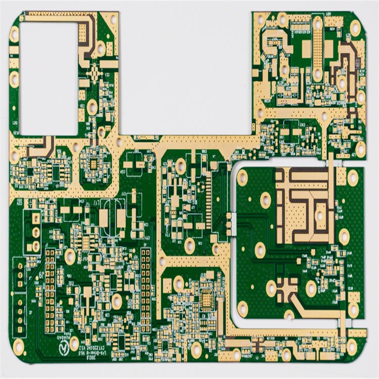
An RF PCB is a non-conductive board made of insulating materials like FR4 on which RF circuit components are mounted. The components are connected by printed copper traces to form the circuits. The board provides mechanical support and electrical connections between components.
RF boards need to be carefully designed as high frequency signals can be affected by trace length, width, dielectric material, component placement, ground planes, and other factors.
Key Components
Some key components found on an RF board include:
Transmitters and Receivers

These send and receive radio signals. Common types are Wi-Fi, Bluetooth, GPS, and cellular.
Antennas
Converts signals between electrical RF current and electromagnetic waves. Different types are used for different frequencies and applications.
Amplifiers
Boosts the power of RF signals for stronger transmission. RF power amplifiers are critical in transmitters.
Filters
Blocks or passes certain RF signal frequencies. Helps eliminate noise and improve signal quality.
Mixers
Combines or separates RF signals at different frequencies. Used in superheterodyne receivers.
Resonators
Oscillates at a fixed RF frequency like a crystal oscillator or MEMS resonator. Provides a frequency reference.
Phase Locked Loops (PLL)
Generates precise, adjustable RF frequencies for tuning. PLL synthesizers provide variable frequency control.
Design Considerations
Key factors to consider when designing an RF PCB include:
- Frequency – The operating frequency impacts component selection, trace widths, and materials used. Higher frequencies need smaller, tightly controlled layouts.
- Impedance Control – Matching impedances properly reduces signal reflections. 50-ohm or 75-ohm traces are common.
- Noise Reduction – Keep analog and digital circuits separated. Use multiple ground planes to isolate noise.
- Shielding – Enclose RF components in shielded compartments to contain electromagnetic interference (EMI).
- Antenna Integration – Carefully position antennas away from other components to optimize radiation pattern. Use RF coax cables to connect.
- Heat Dissipation – Ensure adequate copper fills, vias, and clearance around high-power RF components to dissipate heat.
- Test Points – Include test points to validate RF performance during prototyping and troubleshooting.
Manufacturing RF Boards
Some considerations when manufacturing RF PCBs:
- Use high-quality PCB substrate materials like FR4, Rogers, or polyimide
- Carefully control dielectric thickness and layer count
- Use smaller trace/space widths and tighter tolerances
- Plate traces and vias with gold for optimal conductivity
- Perform impedance testing and RF calibration
- Carry out thorough functional testing at operating frequencies
Overall, RF PCBs require careful engineering and calibration to function correctly at radio frequencies. Attention must be paid to the layout, material selection, modeling, prototyping, and testing.
Frequently Asked Questions
What are some common applications of RF circuit boards?
Some common applications are:
- Wireless communications – Wi-Fi, Bluetooth, 4G/5G, GPS
- Radio transmitters and receivers
- RFID tags and readers
- Satellite communications
- Radar and navigation systems
- Radio broadcasting equipment
What software tools are used to design RF boards?
Some popular RF design software tools are:
- Keysight ADS
- Ansys HFSS
- Cadence Allegro
- Mentor Graphics HyperLynx
- Altium Designer
These provide RF modeling, analysis, layout, and simulation capabilities.
How are components secured to the PCB?
Components are typically soldered to the PCB using surface mount technology (SMT). Some large components may use connectors or spacers. Conductive epoxy or die attach methods can be used for bare die IC mounting.
What is a microstrip transmission line?
A microstrip is a common RF trace used to carry signals. It consists of a flat copper trace on the top layer with a continuous ground plane below on an internal layer. The dimensions and spacing affect its impedance.
How are RF boards tested?
RF boards require specialized RF testing. Some techniques used are:
- Vector network analysis to measure S-parameters
- Spectrum analysis to check frequencies, harmonics, noise
- Power measurements to test amplifiers and transmitters
- Antenna radiation pattern testing
- Time domain reflectometry to test transmission lines
Leave a Reply