Introduction
RF (radio frequency) filters are essential components in many electronic devices and systems. They allow certain frequency bands to pass through while blocking others. Filters are implemented in various ways, but one common approach is to build them as part of a printed circuit board (PCB). This article will provide an overview of RF filter PCB design considerations.
RF Filter Basics
RF filters come in many types, including low-pass, high-pass, bandpass, and bandstop. The goal is to shape the frequency response by allowing desired signals to pass through while attenuating unwanted signals. Key specifications include cutoff frequency, roll-off rate, insertion loss in the passband, and attenuation in the stopband.
Filters are constructed using capacitors and inductors. The values and arrangements of these passive components determine the filter’s behavior. Simple filters can be built with just a few components, while more complex designs require many parts working together.
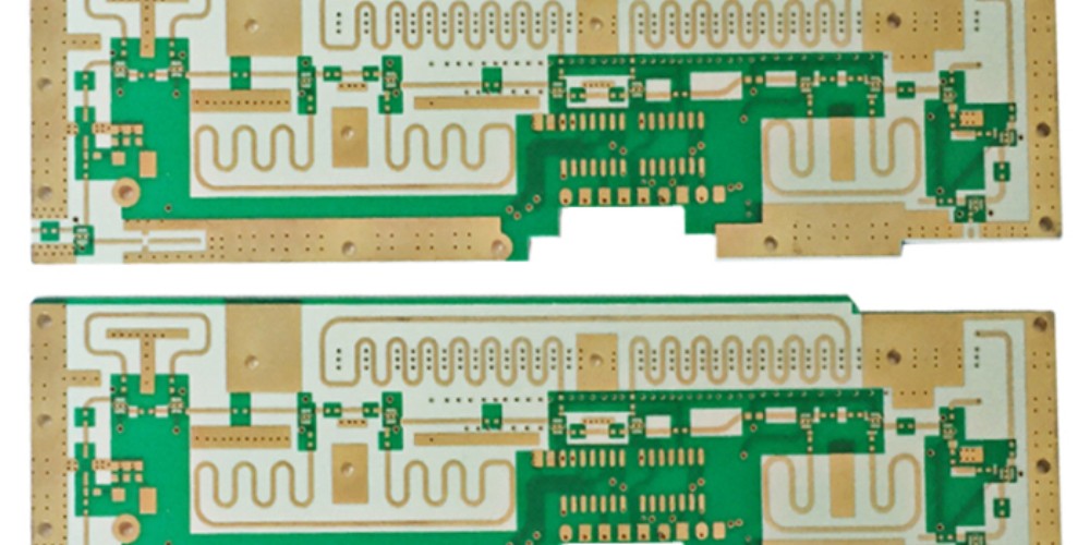
RF Filter PCB Layout

When constructing an RF filter on a PCB, both the circuit schematic and physical layout must be carefully considered. Here are some key guidelines for effective RF filter PCB design:
Component Placement
- Place input and output ports on opposite sides of the board to maximize isolation.
- Position components for shortest possible trace lengths to minimize parasitic effects.
- Group associated capacitors and inductors together in compact arrangements.
Trace Routing
- Use controlled impedance transmission lines for traces between reactive components.
- Avoid right angle bends; use arc or 45 degree bends when necessary.
- Keep high current traces short and wide; longer, low current traces can be narrower.
Grounding
- Use a ground plane layer for shielding and low impedance return paths.
- Connect all filter component grounds directly to the ground plane.
- Use multiple vias to tie ground pads to ground plane at multiple points.
Shielding
- Place ground plane on a layer adjacent to filter components.
- Use via fences or boundaries to isolate filter sections.
- Enclose critical filter areas with grounded metallic shielding.
Simulation and Tuning
Validate the filter design using circuit simulation before layout. Tune the component values as needed to meet requirements. After PCB fabrication, fine tune with network analyzer measurements and component tweaks as needed.
Conclusion
Careful PCB layout is crucial for achieving optimal RF filter performance. Following best practices for component placement, trace routing, grounding, and shielding helps prevent issues like crosstalk, radiated emissions, and impedance mismatches. RF simulations and measured tuning further optimize the filter response. Proper filter PCB design ensures the end product meets technical specifications.
Frequently Asked Questions
Q: What are some common RF filter applications?
A: RF filters are used in wireless devices like cell phones, WiFi routers, Bluetooth modules to select desired signals. They are also used in electronic test equipment, communications infrastructure, and radar systems.
Q: What PCB materials are best for RF filters?
A: High frequency PCBs benefit from low-loss substrate materials like Rogers and Taconic FR-4. These provide stable dielectric properties and tightly controlled impedances.
Q: How can I model RF filters in circuit simulation?
A: You can model filters in SPICE or RF circuit simulators using passive components like inductors, capacitors, and resistors. Include parasitics and transmission line characteristics for accuracy.
Q: What are some alternatives to PCB RF filters?
A: Capped components, cavity filters, and crystal lattice filters are options, but PCB filters offer integration, size, and cost advantages in many applications.
Q: How are tuneable RF filters implemented?
A: Tunable filters use variable capacitors like varactors or MEMS to adjust the center frequency and bandwidth in real time. This allows greater flexibility than fixed filters.
Leave a Reply