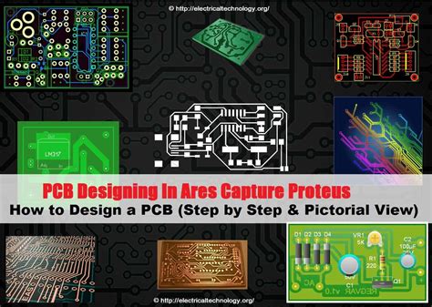
Introduction to PCB Design
Printed Circuit Board (PCB) design is a crucial step in the development of electronic devices. It involves creating a layout of electronic components and the connections between them on a board. The PCB design process can be complex and time-consuming, requiring specialized knowledge and tools. This is where PCB design software comes into play, simplifying the process and enabling designers to create high-quality PCBs efficiently.
What is PCB Design Software?
PCB design software is a computer-aided design (CAD) tool used to create the layout of a PCB. It allows designers to place electronic components on a virtual board, route the connections between them, and generate the necessary files for manufacturing. PCB design software typically includes a suite of tools for schematic capture, layout design, and simulation, making it a comprehensive solution for PCB design.
Benefits of Using PCB Design Software
Using PCB design software offers several benefits, including:
-
Increased Efficiency: PCB design software automates many tasks, such as component placement and routing, reducing the time and effort required to create a PCB layout.
-
Improved Accuracy: PCB design software ensures that the layout adheres to design rules and constraints, minimizing the risk of errors and reducing the need for manual checks.
-
Enhanced Collaboration: Many PCB design software tools allow multiple designers to work on the same project simultaneously, facilitating collaboration and streamlining the design process.
-
Cost Savings: By reducing the time and effort required to create a PCB layout, PCB design software can help lower the overall cost of PCB development.
Types of PCB Design Software
There are several types of PCB design software available, each with its own set of features and capabilities. Some of the most common types include:
1. Schematic Capture Software
Schematic capture software is used to create the schematic diagram of a PCB, which represents the electrical connections between components. It allows designers to add components, define their properties, and create the necessary connections. Schematic capture software typically includes a library of pre-defined components and symbols, making it easy to create complex schematics quickly.
2. Layout Design Software
Layout design software is used to create the physical layout of a PCB, including the placement of components and the routing of connections. It allows designers to define the board shape, layer stackup, and design rules, ensuring that the PCB meets the necessary requirements. Layout design software often includes tools for automatic component placement and routing, as well as 3D visualization and simulation.
3. Simulation Software
Simulation software is used to test and verify the performance of a PCB design before manufacturing. It allows designers to simulate the behavior of the PCB under various conditions, such as signal integrity, power distribution, and thermal performance. Simulation software can help identify potential issues early in the design process, reducing the risk of costly redesigns and delays.

Choosing the Right PCB Design Software
Choosing the right PCB design software can be a daunting task, given the wide range of options available. Here are some factors to consider when selecting PCB design software:
-
Ease of Use: Look for software with a user-friendly interface and intuitive workflow, especially if you are new to PCB design.
-
Feature Set: Consider the specific features and capabilities you need, such as schematic capture, layout design, and simulation.
-
Integration: If you use other design tools, such as mechanical CAD or simulation software, look for PCB design software that integrates well with these tools.
-
Scalability: Choose software that can scale with your needs, whether you are designing simple or complex PCBs.
-
Cost: Consider your budget and the cost of the software, including any recurring fees or maintenance costs.
Here is a comparison of some popular PCB design software options:
| Software | Ease of Use | Feature Set | Integration | Scalability | Cost |
|---|---|---|---|---|---|
| Altium Designer | Moderate | Comprehensive | Good | High | High |
| Eagle | Easy | Moderate | Limited | Moderate | Low |
| KiCad | Moderate | Comprehensive | Limited | High | Free |
| OrCAD | Moderate | Comprehensive | Good | High | High |

PCB Design Workflow
The PCB design workflow typically involves several steps, each of which can be supported by PCB design software. Here is an overview of the typical PCB design workflow:
-
Schematic Capture: The first step is to create the schematic diagram of the PCB, which represents the electrical connections between components. This is done using schematic capture software.
-
Component Placement: Once the schematic is complete, the next step is to place the components on the PCB layout. This is done using layout design software, which allows designers to define the board shape, layer stackup, and design rules.
-
Routing: After the components are placed, the next step is to route the connections between them. This is typically done using autorouting tools, which can automatically route the connections based on the design rules and constraints.
-
Simulation: Before finalizing the PCB design, it is important to simulate its performance to ensure that it meets the necessary requirements. This is done using simulation software, which can test the PCB under various conditions.
-
Manufacturing: Once the PCB design is complete and has been verified through simulation, the final step is to generate the necessary files for manufacturing. This typically includes Gerber files, which are used by PCB manufacturers to fabricate the board.

Best Practices for PCB Design
To ensure the success of your PCB design project, it is important to follow best practices throughout the design process. Here are some key best practices to keep in mind:
-
Start with a Clear Specification: Before starting the design process, make sure you have a clear specification of the PCB’s requirements, including its functionality, size, and performance.
-
Use a Modular Design Approach: Break down the PCB design into smaller, modular sections, which can be designed and tested independently. This can help simplify the design process and make it easier to make changes later on.
-
Follow Design Rules and Guidelines: Adhere to the design rules and guidelines provided by your PCB manufacturer, as well as industry standards such as IPC. This can help ensure that your PCB is manufacturable and reliable.
-
Use Simulation and Testing: Use simulation and testing tools to verify the performance of your PCB design before manufacturing. This can help identify potential issues early on and reduce the risk of costly redesigns.
-
Collaborate with Stakeholders: Collaborate with other stakeholders, such as mechanical designers and manufacturing partners, throughout the design process. This can help ensure that the PCB design meets all necessary requirements and is optimized for manufacturing.
Conclusion
PCB design software is an essential tool for creating high-quality PCBs efficiently and accurately. By understanding the different types of PCB design software available, choosing the right software for your needs, and following best practices throughout the design process, you can ensure the success of your PCB design project.
FAQ
-
What is the difference between schematic capture and layout design software?
Schematic capture software is used to create the schematic diagram of a PCB, which represents the electrical connections between components. Layout design software, on the other hand, is used to create the physical layout of the PCB, including the placement of components and the routing of connections. -
Do I need to use simulation software for my PCB design?
While simulation software is not strictly necessary for all PCB designs, it can be very helpful in identifying potential issues early in the design process, reducing the risk of costly redesigns and delays. Simulation software can test the PCB under various conditions, such as signal integrity, power distribution, and thermal performance. -
How do I choose the right PCB design software for my needs?
When choosing PCB design software, consider factors such as ease of use, feature set, integration with other tools, scalability, and cost. Look for software that meets your specific needs and budget, and that can scale with your future requirements. -
What are some common PCB design mistakes to avoid?
Some common PCB design mistakes to avoid include failing to follow design rules and guidelines, not using simulation and testing tools, not collaborating with other stakeholders, and not starting with a clear specification of requirements. By following best practices and using the right tools, you can minimize the risk of these mistakes. -
How long does the PCB design process typically take?
The length of the PCB design process can vary widely depending on the complexity of the design, the tools and resources available, and the experience of the design team. Simple PCBs can be designed in a matter of hours or days, while more complex designs can take weeks or even months. By using PCB design software and following best practices, you can streamline the design process and reduce the overall time required.
Leave a Reply