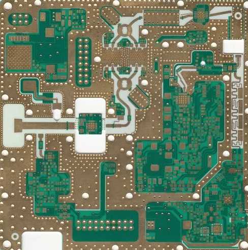
Introduction to Microwave Circuit Boards
Microwave circuit boards are printed circuit boards (PCBs) designed for use in microwave frequencies, typically above 1 GHz. They enable the transmission and processing of high-frequency microwave signals in a wide range of electronic devices including radar systems, satellite communication, wireless infrastructure and microwave ovens.
Microwave circuit boards have some unique design considerations compared to conventional PCBs. The high operating frequencies require careful management of signal integrity issues like reflections, crosstalk and losses. Components and traces are physically smaller, fabrication tolerances are tighter and exotic board materials are often used.
Key Components on Microwave Circuit Boards
Some of the key components found on microwave circuit boards include:
Microwave Integrated Circuits (MICs)
These are active devices like amplifiers, mixers, multipliers, switches and oscillators tailored for microwave frequencies. Gallium arsenide (GaAs) is a popular semiconductor material used for MICs.
Transmission Lines
These conduct microwave signals across the board. Microstrip, stripline and coplanar waveguide are some of the common transmission line structures used.
Microwave Passive Components
Components like directional couplers, power dividers, filters and terminators help process, divide, filter and terminate microwave signals.
Microwave Connectors and Packaging
Specialized connectors and packaging techniques are used to interface the board to other microwave components and minimize unwanted radiation and interference. Common connectors used include SMA, SSMA, 2.92mm and 2.4mm.
Exotic Board Materials
Conventional FR-4 laminates have high losses at microwave frequencies. PTFE, ceramic filled PTFE composites, hydrocarbon ceramics and polyimide laminates are some commonly used low-loss board materials.
Microwave Circuit Board Fabrication

Microwave circuit boards require more expensive fabrication processes with tighter tolerances. Key aspects include:
- Smaller traces and spaces, sometimes less than 0.1mm
- Tight thickness and permittivity control of dielectric materials
- Plated through holes and buried/blind vias for vertical interconnects
- Fine line etching and high-resolution imaging
- Smooth copper finishes to reduce skin effect losses
- Tight impedance control of transmission lines
- Exotic materials incompatible with standard PCB processes
High-end PCB technologies like laser direct imaging (LDI) are commonly used to achieve the requisite quality levels.
Microwave Circuit Board Testing
Testing high-speed signals on microwave circuit boards requires specialized techniques like:
- Vector network analysis to measure S-parameters
- Time-domain reflectometry (TDR) to test impedance and signal integrity
- Thermal imaging to check for hotspots under high-power operation
- Anechoic chambers to evaluate radiation characteristics
- Environmental stress screening (ESS) for robustness under thermal cycling, vibration etc.
Careful modeling and simulation is done in tandem with testing to fully characterize microwave circuit board performance.
Applications of Microwave Circuit Boards
Some common applications and devices that use microwave circuit boards include:
- Radar and satellite communication systems
- 5G and wireless networking equipment
- Microwave radio links
- Microwave test and measurement equipment
- Medical diathermy and imaging devices
- Microwave ovens
- Direct broadcast satellites
- Military electronic warfare and avionics systems
- High-frequency trading systems
Conclusion
Microwave circuit boards enable the processing and transmission of high-frequency signals in the 1-300GHz range. Their design and fabrication demands specialized components, materials, techniques and testing to achieve the exacting performance requirements. With the proliferation of microwave applications, these boards continue to play a key role in many critical electronic systems.
Frequently Asked Questions
What are some key differences between microwave circuit boards and conventional PCBs?
Some key differences are:
- Smaller features and tighter tolerances
- Use of exotic board materials with lower losses
- More complex modeling, analysis and testing needs
- Specialized components and packaging techniques
- Much higher operating frequencies requiring design for signal integrity
What fabrication techniques are commonly used for microwave circuit boards?
High-end techniques like laser direct imaging (LDI) and advanced materials like PTFE composites allow the tight tolerances and performance needed. Plated through holes, blind/buried vias, and smooth copper finishes are also used.
Why are specialized board materials needed for microwave frequencies?
Materials like FR-4 have very high dielectric losses at microwave frequencies, absorbing much of the transmitted energy as heat. Low-loss materials like PTFE, ceramics and polyimides are needed.
What are some common connectors used on microwave circuit boards?
SMA, SSMA, 2.92mm, and 2.4mm connectors are often used. They maintain a consistent impedance match and prevent radiation leakage at microwave frequencies.
How can signal integrity issues be addressed in microwave circuit board design?
Careful matching of trace impedances, terminating unused lines, choosing low-loss materials, minimizing discontinuities, and isolation for critical signals help manage issues like reflections and crosstalk.

Leave a Reply