Introduction to Power Supply Schematics
A power supply is an essential component in any electronic device, providing the necessary voltage and current to power the circuitry. Power supplies come in various types and configurations, ranging from simple linear regulators to complex switching mode power supplies (SMPS). In this article, we will focus on programmable power supplies and their schematic circuits.
What is a Programmable Power Supply?
A programmable power supply is a versatile and adjustable power source that allows users to set and control the output voltage and current according to their specific requirements. Unlike fixed power supplies with predefined output parameters, programmable power supplies offer flexibility and convenience for testing, prototyping, and powering a wide range of electronic devices.
Key Features of Programmable Power Supplies
- Adjustable voltage and current output
- Digital control and monitoring
- Overvoltage and overcurrent protection
- Remote programming and sensing capabilities
- Low noise and ripple characteristics
Understanding the Power Supply Schematic
To design or troubleshoot a programmable power supply, it is crucial to understand the various components and their roles in the schematic circuit. Let’s break down the essential elements of a typical programmable power supply schematic.
Power Transformer
The power transformer is the heart of the power supply, responsible for stepping down the high voltage AC mains to a lower voltage suitable for the circuitry. The transformer also provides isolation between the primary and secondary windings, ensuring safety and preventing ground loops.
Rectifier
The rectifier converts the stepped-down AC voltage from the transformer into pulsating DC voltage. Full-wave rectifiers, such as bridge rectifiers or center-tapped transformers with two diodes, are commonly used in power supply circuits.
Filter Capacitors
Filter capacitors smooth out the pulsating DC voltage from the rectifier, reducing the ripple and providing a more stable DC voltage. The capacitance value depends on the required output current and the acceptable ripple level.
Voltage Regulator
The voltage regulator is responsible for maintaining a constant output voltage despite variations in the input voltage or load current. Linear regulators, such as the popular 78xx series, provide a simple and cost-effective solution for low-power applications. For higher power and efficiency, switching regulators like buck or boost converters are used.
Feedback and Control Circuitry
To make the power supply programmable, additional circuitry is required for monitoring and controlling the output voltage and current. This typically involves:
- Voltage and current sensing circuits
- Analog-to-digital converters (ADCs) for measuring the output parameters
- Digital-to-analog converters (DACs) for setting the desired output levels
- Microcontrollers or digital signal processors (DSPs) for implementing control algorithms and user interface
Protection Circuits
To ensure the safety and reliability of the power supply and connected devices, various protection circuits are incorporated into the schematic. These include:
- Overvoltage protection (OVP): Prevents the output voltage from exceeding a predetermined level, protecting sensitive loads.
- Overcurrent protection (OCP): Limits the output current to a safe value, preventing damage due to short circuits or overloads.
- Thermal shutdown: Disables the power supply if the internal temperature exceeds a safe threshold, preventing overheating and damage.

Designing a Programmable Power Supply Schematic
Now that we understand the key components and their functions, let’s walk through the steps involved in designing a programmable power supply schematic.
Step 1: Determine the Specifications
Before starting the design, clearly define the required specifications for your programmable power supply. This includes:
- Input voltage range (e.g., 110-240 VAC)
- Output voltage range (e.g., 0-30 VDC)
- Maximum output current (e.g., 0-5 A)
- Voltage and current resolution (e.g., 10 mV, 1 mA)
- Ripple and noise requirements (e.g., <1 mVpp)
- Protection features (e.g., OVP, OCP, thermal shutdown)
Step 2: Select the Power Transformer
Choose a suitable power transformer based on the input voltage range and the maximum output power required. The transformer’s secondary voltage should be higher than the maximum desired output voltage to account for the voltage drops across the rectifier, filter, and regulator stages.
Step 3: Design the Rectifier and Filter Stage
Select the appropriate rectifier configuration (e.g., full-wave bridge rectifier) and determine the required filter capacitance based on the desired ripple voltage and maximum output current. Use the following formula to estimate the minimum capacitance:
C = (I_load * t) / (V_ripple)
Where:
– C is the capacitance in farads (F)
– I_load is the maximum load current in amperes (A)
– t is the time period of the rectified waveform (1/2f for full-wave rectification, where f is the line frequency)
– V_ripple is the desired ripple voltage in volts (V)
Step 4: Choose the Voltage Regulator
Select a suitable voltage regulator based on the required output voltage range, maximum output current, and efficiency considerations. For low-power applications, linear regulators like the LM317 or 78xx series can be used. For higher power and efficiency, consider switching regulators such as buck converters (for step-down) or boost converters (for step-up).
Step 5: Implement the Feedback and Control Circuitry
Design the feedback and control circuitry to make the power supply programmable. This involves:
- Voltage and current sensing circuits using resistor dividers or shunt resistors
- ADCs to measure the output voltage and current
- DACs to set the desired output levels
- A microcontroller or DSP to run the control algorithms and user interface
Determine the required resolution and accuracy of the ADCs and DACs based on the desired voltage and current resolution.
Step 6: Add Protection Circuits
Incorporate protection circuits into the schematic to ensure the safety and reliability of the power supply. This includes:
- Overvoltage protection using comparators and crowbar circuits
- Overcurrent protection using current-sensing resistors and comparators
- Thermal shutdown using temperature sensors and comparators
Step 7: Simulate and Refine the Design
Use simulation tools like SPICE or LTspice to simulate the designed schematic and verify its performance. Analyze the output voltage, current, ripple, and transient response under various load conditions. Make necessary adjustments to the component values or circuit topology to meet the desired specifications.
Step 8: Build and Test the Prototype
Once the schematic design is finalized, build a prototype of the programmable power supply on a breadboard or PCB. Test the prototype under different input and load conditions to validate its functionality and performance. Measure the output voltage, current, ripple, and protection features to ensure they meet the specified requirements.

Example Programmable Power Supply Schematic
Here’s an example schematic of a basic programmable power supply using an Arduino microcontroller for control and user interface:
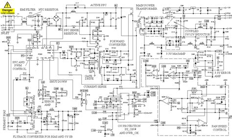
[Insert schematic image or table here]
Components:
– Power transformer: 24 VAC, 5 A
– Bridge rectifier: 10 A, 200 V
– Filter capacitors: 4700 µF, 50 V
– Linear regulator: LM317
– Arduino Uno microcontroller
– LCD display and keypad for user interface
– Voltage and current sensing circuits using resistor dividers and shunt resistors
– ADC: 10-bit resolution (Arduino built-in)
– DAC: 8-bit resolution (PWM-based)
– Overvoltage and overcurrent protection circuits using comparators and MOSFETs
This example provides a starting point for designing a programmable power supply schematic. The actual component values and circuit complexity may vary depending on the specific requirements and features desired.

Frequently Asked Questions (FAQ)
- What is the difference between a linear and switching power supply?
-
A linear power supply uses a linear voltage regulator to maintain a constant output voltage, while a switching power supply uses high-frequency switching techniques to regulate the output. Linear power supplies are simpler and have lower noise, but are less efficient and generate more heat. Switching power supplies are more complex but offer higher efficiency and can handle higher power levels.
-
How do I choose the right voltage regulator for my programmable power supply?
-
The choice of voltage regulator depends on factors such as the required output voltage range, maximum output current, efficiency, and noise requirements. For low-power applications, linear regulators like the LM317 or 78xx series are suitable. For higher power and efficiency, switching regulators like buck or boost converters are preferred.
-
What is the purpose of the filter capacitors in a power supply schematic?
-
Filter capacitors are used to smooth out the pulsating DC voltage from the rectifier stage, reducing the ripple and providing a more stable DC voltage to the regulator. The capacitance value is chosen based on the desired ripple voltage and maximum output current.
-
How do I protect my programmable power supply from overvoltage and overcurrent conditions?
-
Overvoltage protection can be implemented using comparators and crowbar circuits that short the output to ground if the voltage exceeds a predetermined threshold. Overcurrent protection can be achieved using current-sensing resistors and comparators that limit the output current by controlling the voltage regulator or shutting down the power supply.
-
Can I use an Arduino or other microcontrollers to control a programmable power supply?
- Yes, microcontrollers like Arduino or Raspberry Pi can be used to control and monitor a programmable power supply. They provide the necessary digital control, analog measurement, and user interface capabilities. The microcontroller reads the output voltage and current using ADCs, sets the desired output levels using DACs or PWM, and communicates with the user via displays, keypads, or serial interfaces.
Conclusion
Designing a programmable power supply schematic requires a good understanding of the various components and their roles in the power conversion and regulation process. By following the step-by-step approach outlined in this article, you can create a schematic that meets your specific requirements for output voltage, current, protection, and user interface.
Remember to simulate and test your design thoroughly to ensure its performance and reliability. With a well-designed programmable power supply, you can power and test a wide range of electronic devices with ease and flexibility.
Leave a Reply