Understanding Countersink and Counterbore in PCB Design
When designing and manufacturing printed circuit boards (PCBs), it is essential to understand the various techniques used to create holes and cavities for component placement and fastening. Two common methods used in PCB design are countersinking and counterboring. Although these terms may sound similar, they serve different purposes and have distinct characteristics. In this article, we will explore the differences between countersinks and counterbores in PCBs, their applications, and their impact on the overall design and functionality of the board.
What is a Countersink?
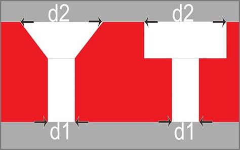
A countersink is a conical-shaped cavity created at the top of a drilled hole in a PCB. The purpose of a countersink is to allow the head of a flathead screw or bolt to sit flush with or below the surface of the PCB when fastened. This technique is commonly used when a low-profile or smooth surface is required, such as in applications where the PCB needs to be mounted flush against another surface or when the protruding screw head may interfere with other components.
The angle of a countersink is typically 82 degrees, which corresponds to the standard angle of a flathead screw. However, other angles, such as 90 or 100 degrees, may be used depending on the specific requirements of the application.
What is a Counterbore?
A counterbore, on the other hand, is a cylindrical cavity created at the top of a drilled hole in a PCB. Unlike a countersink, which has a conical shape, a counterbore has a flat bottom and straight walls. The purpose of a counterbore is to allow the head of a socket head cap screw or bolt to sit flush with or below the surface of the PCB when fastened. This technique is often used when a stronger or more secure connection is required, as the straight walls of the counterbore provide more surface area for the screw head to engage with the PCB.
The depth of a counterbore is typically equal to or slightly greater than the height of the screw head, ensuring that the head is fully recessed within the cavity.
Applications of Countersinks and Counterbores in PCBs
Countersinks and counterbores are used in various applications in PCB design and assembly. Some common uses include:
-
Mounting PCBs: Countersinks and counterbores are frequently used when mounting PCBs to enclosures, chassis, or other surfaces. By creating a flush or recessed cavity for the screw head, the PCB can be securely fastened without the risk of the screw head interfering with other components or causing damage to the board.
-
Component placement: In some cases, countersinks or counterbores may be used to accommodate the mounting of certain components on the PCB. For example, a counterbore may be used to create a cavity for a through-hole component with a large base, allowing it to sit flush with the surface of the board.
-
Electrical grounding: Countersinks and counterbores can also play a role in electrical grounding. By creating a larger surface area for the screw head to contact the PCB, a more secure and reliable electrical connection can be established between the board and the grounding point.
-
Aesthetic considerations: In applications where the appearance of the PCB is important, countersinks and counterbores can help create a cleaner and more professional look by eliminating protruding screw heads and ensuring a flush or recessed mounting surface.
Designing Countersinks and Counterbores in PCBs
When incorporating countersinks or counterbores into a PCB design, several factors must be considered to ensure proper functionality and manufacturability:
-
Hole size: The diameter of the drilled hole should be carefully selected based on the size of the screw or bolt being used. The hole should be large enough to allow the screw to pass through easily but not so large that it compromises the structural integrity of the PCB.
-
Countersink/Counterbore depth: The depth of the countersink or counterbore should be specified based on the height of the screw head and the desired level of recess. It is important to ensure that the depth is sufficient to fully accommodate the screw head without leaving any protrusions.
-
Pad size: The size of the copper pad surrounding the hole should be large enough to provide adequate support for the screw head and to ensure a secure electrical connection if required. The pad size should also take into account the diameter of the countersink or counterbore.
-
Placement: The location of countersinks and counterbores on the PCB should be carefully planned to avoid interference with other components, traces, or features. It is also important to consider the accessibility of the screws or bolts during the assembly process.
-
Manufacturing capabilities: When designing countersinks and counterbores, it is crucial to consult with the PCB manufacturer to ensure that the specified dimensions and tolerances are within their capabilities. Some manufacturers may have limitations on the minimum or maximum sizes, depths, or angles that they can produce.
Comparing Countersinks and Counterbores
While countersinks and counterbores serve similar purposes in PCB design, they have distinct characteristics that make them suitable for different applications. The following table summarizes the key differences between countersinks and counterbores:
| Feature | Countersink | Counterbore |
|---|---|---|
| Shape | Conical | Cylindrical |
| Purpose | Accommodate flathead screws | Accommodate socket head cap screws |
| Angle | Typically 82°, 90°, or 100° | Not applicable (straight walls) |
| Depth | Varies based on screw head height | Equal to or slightly greater than screw head height |
| Strength | Provides less surface area for screw engagement | Provides more surface area for screw engagement |
| Appearance | Creates a smooth, flush surface | Creates a recessed cavity |
Frequently Asked Questions (FAQ)
-
Q: Can countersinks and counterbores be used together in the same PCB?
A: Yes, countersinks and counterbores can be used together in the same PCB design. The choice between the two depends on the specific requirements of each mounting point or component. -
Q: Are there any limitations on the size of countersinks or counterbores in PCBs?
A: The size of countersinks and counterbores is typically limited by the capabilities of the PCB manufacturer. It is important to consult with the manufacturer to ensure that the desired dimensions and tolerances are achievable. -
Q: Can countersinks or counterbores be added to an existing PCB?
A: While it is possible to add countersinks or counterbores to an existing PCB, it is generally more challenging and expensive than incorporating them during the initial design and manufacturing process. Adding these features post-production may require specialized equipment and may risk damaging the existing components or traces. -
Q: How do countersinks and counterbores affect the cost of PCB manufacturing?
A: The inclusion of countersinks and counterbores in a PCB design may increase the overall manufacturing cost, as they require additional drilling and machining operations. The cost impact depends on factors such as the number of holes, the specified dimensions, and the manufacturing capabilities of the chosen supplier. -
Q: Are there any specific design guidelines for placing countersinks or counterbores near the edges of a PCB?
A: When placing countersinks or counterbores near the edges of a PCB, it is important to maintain sufficient distance from the edge to ensure structural integrity and avoid potential damage during handling or assembly. The specific guidelines may vary depending on the PCB material, thickness, and manufacturer’s recommendations. It is advisable to consult with the PCB manufacturer and adhere to their design rules and guidelines.
Conclusion
Understanding the difference between countersinks and counterbores is crucial for designing and manufacturing high-quality, functional PCBs. While both techniques involve creating cavities in drilled holes, they serve distinct purposes and have specific characteristics that make them suitable for different applications.
Countersinks, with their conical shape, are primarily used to accommodate flathead screws and create a flush or smooth surface on the PCB. They are commonly used in applications where a low profile or seamless appearance is desired.
Counterbores, on the other hand, feature a cylindrical shape with straight walls and a flat bottom. They are designed to accommodate socket head cap screws and provide a stronger, more secure connection. Counterbores are often used when a more robust mechanical fastening is required.
When incorporating countersinks or counterbores into a PCB design, it is essential to consider factors such as hole size, cavity depth, pad size, placement, and manufacturing capabilities. By carefully planning and specifying these features, designers can ensure that the PCB meets the desired functional and aesthetic requirements while maintaining manufacturability and cost-effectiveness.
As with any aspect of PCB design, effective communication and collaboration with the manufacturing partner are key to successful implementation. By understanding the differences between countersinks and counterbores and their respective applications, designers can make informed decisions and create PCBs that are optimized for their intended use.

Leave a Reply