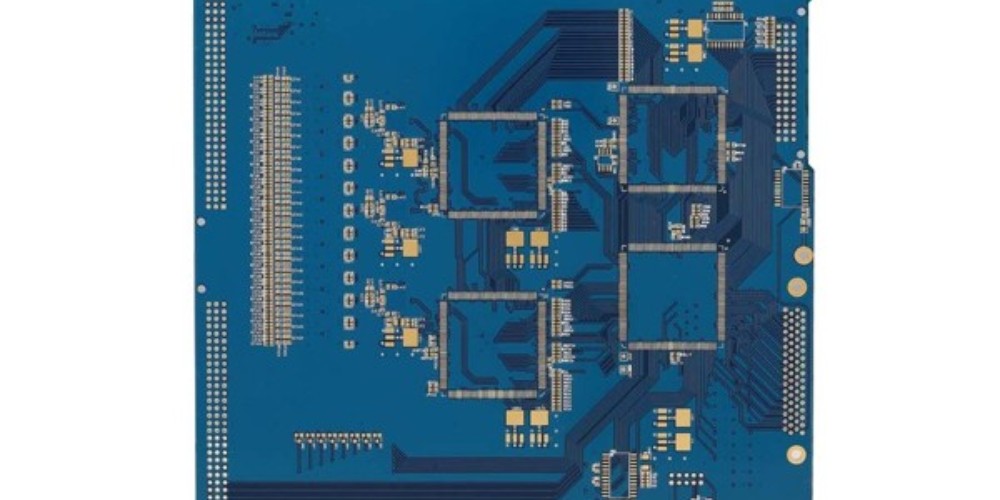
Introduction
rf pcb connectors are an important component in radio frequency (RF) circuits and systems. They allow RF signals to be transferred from one part of a circuit board or system to another. Choosing the right RF connector requires careful consideration of frequency range, power handling, impedance matching, and other factors. This article provides an overview of common types of RF connectors used on printed circuit boards (PCBs) and guidance on selecting the appropriate connector.
Common Types of RF Connectors
Coaxial Connectors
Coaxial connectors are commonly used for RF signals up to GHz frequencies. They have a center conductor surrounded by a shield, providing controlled impedance. Popular types include:
- SMA (SubMiniature version A) – used up to 18 GHz
- SMB (SubMiniature version B) – used up to 4 GHz
- SMC (SubMiniature version C) – used up to 10 GHz
- SSMA (Subminiature Snap-On) – used up to 26.5 GHz
Edge Launch Connectors
These connectors mount to the edge of a PCB and allow transitioning from microstrip or coplanar waveguide transmission lines on the PCB to coaxial cables. They are useful for high frequency applications up to 50 GHz. Common types are SMP and V connectors.
Board-to-Board Connectors
Allow connecting PCBs together with controlled impedance at microwave frequencies. Examples include:
- Button connectors – easy to mate and unmate
- Compression mount connectors – uses compression force for reliable contact
- Spring loaded connectors – pogo pins provide reliable contact
Choosing the Right RF Connector

Here are key factors to consider when selecting an RF connector:
- Frequency Range – Choose a connector suitable for your operating frequency. Check manufacturer specs.
- Impedance – Match connector impedance to transmission lines (usually 50 ohms).
- Power Handling – Ensure connector is rated for required power levels.
- Size – Consider physical size limitations of your PCB.
- Durability – Pick robust connectors if subject to vibration or frequent mating cycles.
- Cost – Weigh benefits of more expensive connector types for your application.
Properly matching connector characteristics to your PCB and RF system requirements results in optimized signal integrity through connections.
Frequently Asked Questions
What is return loss and why does it matter for RF connectors?
Return loss indicates how much RF power is reflected back from a connector, causing impedance mismatch. Minimizing return loss via well-matched connectors optimizes power transfer and reduces losses.
How do I determine the rated lifetime durability of an RF connector?
Manufacturers provide durability specs based on maximum number of mating cycles. This depends on connector design – compression mount connectors may be rated for 500 cycles, while precision connectors can exceed 10,000 cycles.
What is a weatherproof RF connector?
Weatherproof RF connectors feature rubber sealing sleeves and threaded couplings to protect against dust and moisture when used in harsh outdoor environments. Common types are N-Connectors and SMA.
When should I use board-to-board RF connectors vs. cables?
Board-to-board connectors eliminate cable losses at microwave frequencies. Cables add attenuation, so direct board mating is preferred for very high frequency short connections. Cables are more flexible for long or movable connections.
How do I ensure good electromagnetic compatibility (EMC) with RF connectors?
Shielded connectors, proper grounding, and filtering help prevent electromagnetic interference issues. EMC/EMI testing also helps validate acceptable RF connector performance.

Leave a Reply