Introduction to PCB Stackup
Printed Circuit Board (PCB) stackup refers to the arrangement of copper and insulating layers that make up a PCB. It is a crucial aspect of PCB design, as it determines the board’s electrical properties, mechanical strength, and manufacturability. Proper PCB stackup planning is essential to ensure that the board meets the desired performance requirements while minimizing manufacturing costs and time-to-market.
In this comprehensive guide, we will explore the fundamentals of PCB stackup planning, including the different types of stackups, the materials used, and the best practices for designing an optimal stackup. We will also discuss the importance of signal integrity, power integrity, and electromagnetic compatibility (EMC) in PCB stackup planning.
Types of PCB Stackups
There are three main types of PCB stackups:
- Single-sided PCB stackup
- Double-sided PCB stackup
- Multi-layer PCB stackup
Single-Sided PCB Stackup
A single-sided PCB stackup consists of a single copper layer on one side of the insulating substrate. This type of stackup is the simplest and most cost-effective, but it has limited routing capabilities and is suitable only for very simple circuits.
Double-Sided PCB Stackup
A double-sided PCB stackup has copper layers on both sides of the insulating substrate. This type of stackup offers more routing flexibility than a single-sided stackup and is suitable for moderately complex circuits. However, it still has limitations in terms of signal integrity and power distribution.
Multi-Layer PCB Stackup
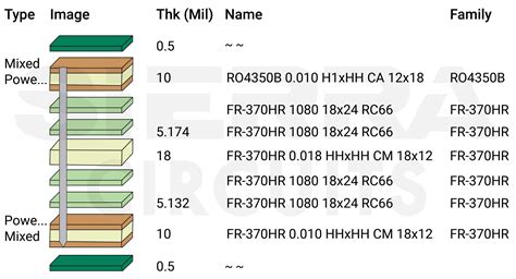
A multi-layer PCB stackup consists of multiple copper layers separated by insulating layers. This type of stackup offers the highest level of routing flexibility and is suitable for complex circuits with high-speed signals and power distribution requirements. Multi-layer stackups can have anywhere from four to over thirty layers, depending on the complexity of the circuit.

Materials Used in PCB Stackups
The choice of materials used in a PCB stackup has a significant impact on the board’s electrical and mechanical properties. The most common materials used in PCB stackups are:
- FR-4 (Flame Retardant 4)
- High-Tg FR-4
- Polyimide
- Rogers materials
FR-4
FR-4 is the most widely used material for PCB substrates. It is a composite material made of woven fiberglass cloth with an epoxy resin binder. FR-4 has good mechanical strength, thermal stability, and electrical insulation properties. It is also relatively inexpensive and easy to manufacture.
High-Tg FR-4
High-Tg FR-4 is a variant of FR-4 with a higher glass transition temperature (Tg). This material offers better thermal stability and lower thermal expansion than standard FR-4, making it suitable for high-reliability applications.
Polyimide
Polyimide is a high-performance polymer material that offers excellent thermal stability, chemical resistance, and mechanical strength. It is often used in aerospace and military applications where reliability is critical.
Rogers Materials
Rogers materials are a family of high-frequency laminate materials designed for use in RF and microwave applications. These materials offer low dielectric loss, stable dielectric constant, and low moisture absorption, making them ideal for high-speed digital and analog circuits.

Best Practices for PCB Stackup Planning
To design an optimal PCB stackup, consider the following best practices:
-
Define the board’s requirements: Clearly define the board’s electrical, mechanical, and environmental requirements before starting the stackup design process.
-
Choose the appropriate number of layers: Select the minimum number of layers required to meet the board’s routing and power distribution needs. More layers increase the board’s complexity and cost.
-
Use symmetrical stackups: Whenever possible, use symmetrical stackups to minimize warpage and improve the board’s mechanical stability.
-
Manage signal integrity: Ensure proper impedance control, minimize crosstalk, and avoid signal reflection by carefully selecting layer arrangements, trace widths, and spacing.
-
Optimize power distribution: Use dedicated power and ground planes to minimize impedance and ensure an adequate power supply to all components.
-
Consider manufacturability: Design the stackup with manufacturing constraints in mind, such as minimum trace width and spacing, via size and spacing, and drill aspect ratios.

Signal Integrity in PCB Stackup Planning
Signal integrity refers to the ability of a PCB to maintain the quality of high-speed signals as they travel through the board. Poor signal integrity can lead to signal distortion, crosstalk, and electromagnetic interference (EMI). To ensure good signal integrity, consider the following factors in PCB stackup planning:
-
Impedance control: Match the impedance of the traces to the characteristic impedance of the signal source and load to minimize reflections and signal distortion.
-
Crosstalk reduction: Minimize crosstalk between adjacent traces by increasing the spacing between them or using guard traces.
-
Differential pair routing: Route differential pairs on the same layer and with equal length to maintain signal integrity.
-
Via optimization: Minimize the number of vias and place them strategically to reduce signal distortion and reflections.
Power Integrity in PCB Stackup Planning
Power integrity refers to the ability of a PCB to provide a stable and clean power supply to all components. Poor power integrity can lead to voltage fluctuations, noise, and EMI. To ensure good power integrity, consider the following factors in PCB stackup planning:
-
Power plane placement: Place power planes close to the components they supply to minimize impedance and voltage drop.
-
Decoupling capacitor placement: Place decoupling capacitors close to the power pins of components to minimize high-frequency noise.
-
Split power planes: Use split power planes to isolate noisy power supplies from sensitive analog circuits.
-
Via stitching: Use via stitching to connect power planes on different layers and minimize impedance.
Electromagnetic Compatibility (EMC) in PCB Stackup Planning
EMC refers to the ability of a PCB to operate without causing or being affected by electromagnetic interference (EMI). Poor EMC can lead to signal integrity issues, power integrity problems, and regulatory compliance failures. To ensure good EMC, consider the following factors in PCB stackup planning:
-
Layer shielding: Use ground planes to shield sensitive signals from EMI.
-
Edge plating: Use edge plating to create a continuous shield around the board’s perimeter.
-
Trace routing: Route traces away from board edges and connectors to minimize EMI.
-
Filtering: Use filters to suppress high-frequency noise and minimize EMI.
PCB Stackup Planning Tools
There are several software tools available to assist with PCB stackup planning. These tools can help designers optimize layer arrangements, calculate impedance, and ensure manufacturability. Some popular PCB stackup planning tools include:
- Altium Designer
- Cadence Allegro
- Mentor Graphics Expedition
- Zuken CR-8000
Conclusion
PCB stackup planning is a critical aspect of PCB design that directly impacts the board’s electrical performance, mechanical stability, and manufacturability. By understanding the different types of stackups, materials, and best practices for stackup design, engineers can create optimal PCBs that meet the desired requirements while minimizing costs and time-to-market.
Effective PCB stackup planning requires careful consideration of signal integrity, power integrity, and EMC. By using appropriate design techniques and software tools, designers can ensure that their PCBs operate reliably and meet regulatory compliance standards.
Frequently Asked Questions (FAQ)
-
What is the difference between a single-sided and double-sided PCB stackup?
A single-sided PCB stackup has a copper layer on only one side of the insulating substrate, while a double-sided stackup has copper layers on both sides. Double-sided stackups offer more routing flexibility and are suitable for moderately complex circuits. -
What is the purpose of using high-Tg FR-4 material in PCB stackups?
High-Tg FR-4 material offers better thermal stability and lower thermal expansion than standard FR-4. This makes it suitable for high-reliability applications where the PCB may be exposed to extreme temperatures or temperature fluctuations. -
Why is it important to use symmetrical stackups in PCB design?
Symmetrical stackups help minimize warpage and improve the board’s mechanical stability. Warpage can cause issues during the assembly process and lead to reliability problems in the finished product. -
What is the role of decoupling capacitors in power integrity?
Decoupling capacitors are placed close to the power pins of components to minimize high-frequency noise. They act as local energy storage devices, providing a stable power supply to the components and reducing the impact of voltage fluctuations on the power planes. -
How can you minimize electromagnetic interference (EMI) in a PCB?
There are several techniques to minimize EMI in a PCB, including: - Using ground planes to shield sensitive signals
- Implementing edge plating to create a continuous shield around the board’s perimeter
- Routing traces away from board edges and connectors
- Employing filters to suppress high-frequency noise
By carefully planning the PCB stackup and following best practices for signal integrity, power integrity, and EMC, designers can create high-quality, reliable PCBs that meet the demands of today’s complex electronic systems.
Leave a Reply