RF & Microwave Blog
-
PCB Basics knowledge
Posted by
–
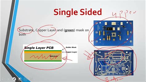
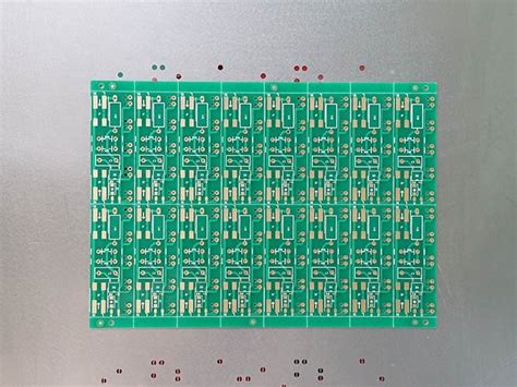
Read more: PCB Basics knowledgeWhat is a PCB? A printed circuit board, or PCB, is the foundation of nearly all modern electronic devices. PCBs are flat boards made of insulating materials like fiberglass, with conductive copper traces printed on them to connect various electronic components. The components – such as resistors, capacitors, and integrated […]
-
What Are Commonly Used Components on PCBs
Posted by
–
 Read more: What Are Commonly Used Components on PCBs
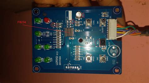
Introduction to PCB Components Printed circuit boards (PCBs) form the backbone of virtually all modern electronic devices. They provide a platform to mechanically support and electrically connect various electronic components using conductive tracks, pads and other features. The components mounted on PCBs are what give the circuit board its functionality. […]
-
 Read more: How to Identify Parts and Components on the PCB of a Mobile Cell Phone
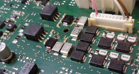
Introduction to PCB Components A mobile cell phone is a complex electronic device that consists of various components mounted on a Printed Circuit Board (PCB). The PCB serves as the backbone of the phone, connecting all the components and allowing them to function together. Understanding the different parts and components […]
-
 Read more: Goldfinger gold plated PCB board quality issues and measures
Introduction to Goldfinger PCBs Goldfinger PCBs, also known as gold plated printed circuit boards, are a type of high-quality PCB that uses a layer of gold plating over the copper traces and pads. The gold plating provides several benefits, including improved corrosion resistance, better electrical conductivity, and enhanced solderability. These […]
-
What is heavy copper PCB
Posted by
–
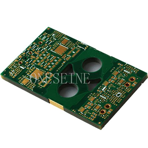 Read more: What is heavy copper PCB
Introduction to Heavy Copper PCB Heavy Copper PCBs, also known as thick copper PCBs or high current PCBs, are printed circuit boards that feature thicker copper traces than standard PCBs. These specialized boards are designed to handle higher currents and provide better thermal management, making them ideal for applications that […]
-
Avoid 10 Common PCB Hand Soldering Problems
Posted by
–
 Read more: Avoid 10 Common PCB Hand Soldering Problems
1. Cold Solder Joints Cold solder joints occur when the solder does not melt completely, resulting in a dull, lumpy appearance. This can happen due to insufficient heat, improper fluxing, or moving the joint before the solder has solidified. To avoid cold solder joints: – Ensure your soldering iron is […]
-
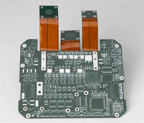 Read more: Why use rigid flex PCB than flexible PCB in electronic project
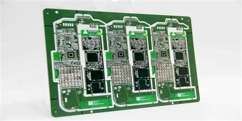
Introduction to Rigid-Flex PCBs and their Advantages Rigid-Flex PCBs are a unique combination of rigid and flexible printed circuit boards that offer numerous advantages over traditional flexible PCBs in electronic projects. This innovative technology allows for the integration of both rigid and flexible substrates into a single circuit board, enabling […]
-
What Do Modern Motherboards Include
Posted by
–
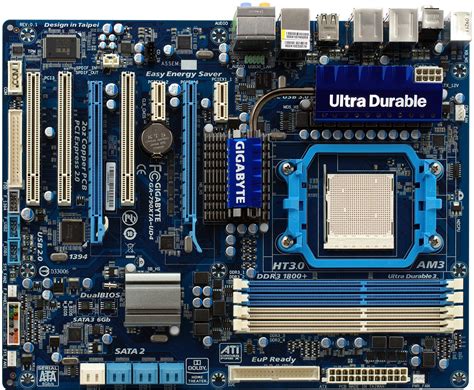 Read more: What Do Modern Motherboards Include
Key Motherboard Features and Specifications Feature Description CPU Socket Connects the processor to the motherboard. Different CPU sockets support specific processor generations and brands (Intel or AMD). Chipset The “brain” of the motherboard. Chipsets manage data flow between processor, RAM, storage, and peripherals. Newer chipsets enable faster components and more […]
-
All You Need to Know About FR 4 PCB
Posted by
–
 Read more: All You Need to Know About FR 4 PCB
What is an FR4 PCB? FR4 PCB, also known as Flame Retardant 4 Printed Circuit Board, is a type of PCB material that is widely used in the electronics industry. It is made from a composite material consisting of woven fiberglass cloth with an epoxy resin binder that is flame […]
-
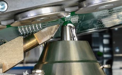
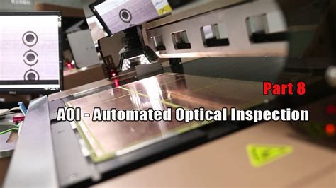 Read more: What Is Automated Optical Inspection AOI in A PCB
Introduction to AOI in PCB Manufacturing Automated Optical Inspection (AOI) is a critical process in the manufacturing of Printed Circuit Boards (PCBs). It is a non-contact method that uses advanced imaging technology to inspect the quality of PCBs during various stages of production. AOI systems are designed to detect and […]
Recent Posts
- How to Select Material for Your PCBs from Cost and Reliability Considerations
- Problems of EMC Technology Application in PCB Design of Electronic Devices and the Strategies
- Fabrication Technology on Flex-Rigid PCB Window
- Problems of High-Frequency and High-Speed Multilayer PCB Fabrication and Their Solutions
- Key Difficulties and Tips for Backplane PCB Fabrication