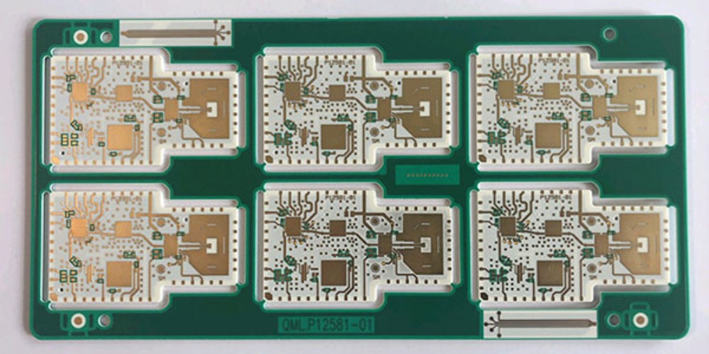
Introduction
High frequency circuit boards are designed to operate at high frequencies, typically in the gigahertz (GHz) range. They are commonly used in wireless communications, radars, satellites, and other high frequency electronic systems. The main challenges in high frequency circuit design are minimizing loss, controlling impedance, and managing interference. Careful layout and material selection are critical for the performance of these boards.
Materials and Construction
The substrate material used for high frequency boards needs to have low dielectric loss. Common materials include PTFE composites, ceramic filled PTFE, hydrocarbon ceramics, and polyimide films. Copper is the most common conductor used. To manage loss, high frequency boards often use thicker copper layers compared to standard PCBs.
Special care needs to be taken in layout to control impedance based on transmission line theory. Features like voids, splits, and antipads can cause impedance discontinuities, which lead to reflections. Minimizing board thickness and lamination variations also helps control impedance.
Common High Frequency Board Constructions:
- PTFE composites (woven glass reinforced)
- Ceramic filled PTFE
- Polyimide films
- Thick copper layers (2+ oz.)
- Tight impedance control
Layout Techniques

Here are some key layout techniques used in high frequency board design:
Transmission Lines
Matched impedance transmission lines need to be routed for high frequency traces to avoid reflections. Microstrip, stripline, and coplanar waveguide are common transmission line structures used.
Vias
Minimizing vias is critical, as they can cause discontinuities. When needed, backdrilling vias after lamination reduces their impact. Stubless, filled and stacked vias are also used.
Decoupling
Closely spaced high frequency decoupling capacitors are used to provide charge to ICs. 0201 and 01005 size capacitors are common to fit dense designs.
Shielding
Strategic use of ground planes and copper fills creates shielding between circuits. Fences and channels isolate critical traces.
Simulations
Modeling techniques like EM simulations are used to virtually prototype boards and identify issues before fabrication.
Applications
Some common applications of high frequency circuit boards include:
- Cellular base stations
- Radar and satellite systems
- High speed data links
- Radio transceivers
- Aerospace and defense electronics
- Research lab test equipment
The need for higher operating frequencies continues to drive high frequency circuit board technology for cutting edge systems. Tight electrical and mechanical design principles must be followed to ensure optimal performance.
Frequently Asked Questions
What are some key materials used in high frequency boards?
Some common materials are PTFE composites, ceramic filled PTFE, hydrocarbon ceramics, and polyimide films. Thick copper layers are also used to minimize loss.
How can you control impedance on high frequency boards?
Careful layout, minimizing thickness variations, and managing features like voids and splits help control impedance based on transmission line theory.
Why is via design important?
Vias can cause impedance discontinuities, so minimizing vias is critical. Backdrilling, filled vias, and stubless structures help when vias are needed.
What are some examples of high frequency applications?
Cellular base stations, radar/satellite, high speed data links, radio transceivers, aerospace/defense, and lab equipment all use high frequency boards.
How does shielding help high frequency designs?
Strategic use of ground planes, fills, fences, and channels creates shielding between circuits to minimize interference.

Leave a Reply