Introduction to Signal Conditioners
A signal conditioner is an electronic device that converts one type of electronic signal into another type of signal. Its primary purpose is to convert a signal that may be difficult to read by conventional instrumentation into a more easily read format.
Signal conditioners can include amplifiers, filters, converters (such as frequency-to-voltage or current-to-voltage), isolators, and other types of circuitry that manipulate the signal into a more desirable form factor and amplitude for a data acquisition system or other measurement device.
Common types of signal conditioning include:
| Type | Description |
|---|---|
| Amplification | Increases the power, voltage, or current of a signal |
| Attenuation | Decreases the amplitude of a signal |
| Filtering | Removes unwanted frequency components from a signal |
| Isolation | Prevents stray currents between two circuits sharing a common signal |
| Conversion | Changes the type of signal (e.g. current to voltage) |
| Linearization | Produces an output that is directly proportional to the input |
Signal conditioners are widely used across many industries to interface various types of sensors and transducers to measurement and data acquisition equipment. They play a vital role in ensuring clean, accurate signals for reliable system monitoring and control.
PCB Piezotronics’ New DC Signal Conditioner
Features and Specifications
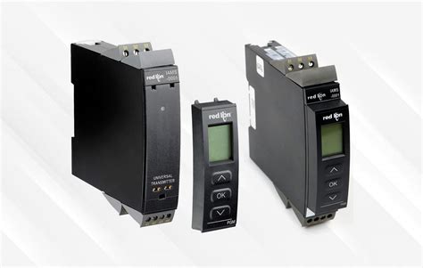
PCB Piezotronics, a leading provider of sensors and related instrumentation, has recently introduced a new signal conditioner specifically designed for use with DC-operated sensors such as pressure transducers, load cells, and torque sensors. The Model 485B36 DC Signal Conditioner offers a range of features to simplify sensor setup and optimize performance:
- Voltage or current excitation
- Bridge completion for quarter and half bridge sensors
- Shunt calibration
- Auto-zero and auto-balance functions
- Selectable low-pass filtering
- Dual mode outputs (voltage and current)
The unit provides a regulated 12 VDC excitation source configurable for 2-wire or 3-wire sensors. It can deliver excitation currents up to 30 mA. A precision current source is also available for sensors requiring constant current excitation.
For strain gage type sensors, the 485B36 has built-in bridge completion resistors that can be configured for 120Ω, 350Ω, and 1 kΩ bridges. Shunt calibration resistors are also included for verification and troubleshooting purposes.
Key specifications of the Model 485B36 are summarized in the table below:
| Parameter | Value |
|---|---|
| Excitation Voltage | 12 VDC |
| Excitation Current | 30 mA max |
| Constant Current Excitation | 0 to 12 mA |
| Bridge Completion | 120Ω, 350Ω, 1 kΩ |
| Gain Range | 1 to 11,000 |
| Low-Pass Filter Frequencies | 2 Hz to 20 kHz |
| Voltage Output | ±10 V |
| Current Output | 4-20 mA |
The wide gain range allows the conditioner to be used with a variety of sensor types and full scale ranges. Low-pass filter frequencies are selectable from 2 Hz to 20 kHz to remove high frequency noise and prevent aliasing when used with data acquisition systems.
Both voltage (±10 V) and 4-20 mA current outputs are provided, which are compatible with most DAQ hardware and industrial control systems. The current output allows reliable signal transmission over long cable lengths.
Applications
The 485B36 signal conditioner is suitable for use in a wide range of test and measurement applications across various industries:
Automotive and Aerospace
- Vehicle and aircraft structural testing
- Brake and tire testing
- Wind tunnel testing
- Crash and impact testing
Industrial Automation
- Factory process monitoring
- Quality control
- Robotic force sensing
- Hydraulic and pneumatic system monitoring
Research and Development
- University labs
- Government research facilities
- Product development testing
- Materials testing
Power Generation and Energy
- Wind turbine monitoring
- Oil and gas pressure/flow measurements
- Pipeline leak detection
- Nuclear power plant instrumentation
The unit’s versatile input and output options, compact size, and robust industrial design make it an ideal choice for both laboratory and field use. Its compatibility with industry-standard interfaces simplifies integration with existing measurement systems.

Proper Selection and Installation of Signal Conditioners
Matching Sensors and Conditioners
Selecting the right signal conditioner for a particular sensor is critical to achieving optimal system accuracy and reliability. Key factors to consider when pairing sensors and conditioners include:
- Sensor type (bridge, voltage, current, etc.)
- Full scale output range
- Excitation requirements
- Required amplifier gain
- Desired frequency response
- Environmental conditions (temperature, vibration, etc.)
It’s important to consult the sensor manufacturer’s specifications to determine the appropriate excitation levels and input/output characteristics. The conditioner should provide the necessary excitation voltage or current, as well as accommodate the sensor’s full scale output range.
The amplifier gain should be selected to scale the sensor output to the desired voltage range for the data acquisition system. Gain is calculated as:
Gain = Vout / (Sensitivity × Full Scale)
where:
– Vout is the desired full scale output voltage
– Sensitivity is the sensor’s output per engineering unit
– Full Scale is the maximum engineering value to be measured
For example, if a pressure transducer has a sensitivity of 3 mV/psi and a full scale range of 100 psi, and ±10 V output is desired, the required gain would be:
Gain = 10 V / (0.003 V/psi × 100 psi) = 333.33
The low-pass filter cutoff frequency should be set based on the desired frequency response for the application. As a general rule, the cutoff frequency should be at least 10 times the highest frequency of interest to avoid attenuating important signal content.
Proper Wiring and Grounding Practices
Correct wiring and grounding are essential to ensure the integrity of sensor signals and prevent unwanted noise pickup. Some key best practices include:
- Use shielded, twisted pair cabling for sensor connections
- Keep sensor wiring away from power cables and other noise sources
- Ensure proper shield termination at the conditioner end only (to avoid ground loops)
- Use appropriate grounding techniques (single-point, star, etc.) based on the application
- Provide adequate strain relief for cables to prevent damage or intermittent connections
When wiring bridge type sensors, it’s important to maintain the proper polarity and orientation of the excitation and signal lines. Incorrect wiring can result in erratic or erroneous readings.
The signal conditioner should be mounted in a location that minimizes exposure to extreme temperatures, vibration, and electromagnetic interference (EMI). If the unit will be used in a harsh environment, an enclosure with appropriate IP rating should be utilized.

Calibration and Maintenance
Calibration Procedures
Regular calibration of signal conditioners is necessary to maintain measurement accuracy over time. The calibration process involves applying known inputs to the sensor and adjusting the conditioner’s gain and offset to match the expected outputs.
Most signal conditioners provide some form of calibration functionality, such as shunt calibration or null adjustment. Shunt calibration involves temporarily connecting a precision resistor across one leg of the sensor bridge to simulate a known load or deflection. The conditioner’s gain is then adjusted to produce the expected output voltage.
Null adjustment, or auto-zero, is used to compensate for any offset in the sensor or conditioner circuitry. This is typically done by disconnecting or unloading the sensor and adjusting the conditioner’s zero potentiometer until the output reads zero.
Calibration should be performed at regular intervals based on the specific requirements of the application and the stability of the sensor and conditioner. More frequent calibration may be necessary in critical applications or harsh environments.
It’s important to use accurate, traceable calibration standards and follow the manufacturer’s recommended calibration procedures. Calibration data should be recorded and stored for traceability and quality control purposes.
Preventive Maintenance
In addition to regular calibration, signal conditioners require periodic preventive maintenance to ensure reliable long-term operation. Some key maintenance tasks include:
- Visual inspection for signs of damage, corrosion, or loose connections
- Cleaning of external surfaces and connector contacts
- Verification of power supply voltages and currents
- Functional Testing of all input and output channels
- Replacement of any damaged or worn components
Maintaining a clean, dry, and temperature-controlled environment for the conditioner can help prolong its service life and prevent premature failure. Proper cable management and strain relief can also help minimize wear and tear on the unit’s connectors.
Following the manufacturer’s recommended maintenance schedule and procedures can help catch potential problems early and avoid costly downtime or data loss.

FAQ
What types of sensors can be used with PCB’s 485B36 signal conditioner?
The 485B36 is compatible with a wide range of DC-operated sensors, including pressure transducers, load cells, torque sensors, and strain gages. It can accommodate full bridge, half bridge, and quarter bridge configurations, as well as voltage and current output sensors.
What is the difference between voltage and current excitation?
Voltage excitation involves applying a constant voltage across the sensor’s input terminals, while current excitation uses a constant current source. Current excitation is often used with resistive sensors to minimize the effects of lead wire resistance. The 485B36 provides both voltage and current excitation options.
How do I select the appropriate gain setting for my sensor?
The gain should be selected based on the sensor’s sensitivity and the desired full scale output voltage of the conditioner. Gain is calculated as the output voltage divided by the product of the sensor’s sensitivity and full scale range. Consult the sensor manufacturer’s specifications and the conditioner’s gain range to determine the optimal setting.
Can the 485B36 be used in harsh environments?
The 485B36 is designed for industrial use and can tolerate a wide range of environmental conditions. However, for extreme temperatures, vibration, or moisture exposure, additional protective measures such as enclosures or conformal coating may be necessary. Always consider the specific environmental requirements of your application when selecting a signal conditioner.
How often should I calibrate my signal conditioner?
Calibration frequency depends on the stability of the sensor and conditioner, as well as the accuracy requirements of the application. In general, calibration should be performed at least annually, or more frequently if required by industry standards or quality control procedures. It’s also a good idea to recalibrate after any major maintenance or repair work.
Conclusion
Signal conditioners play a crucial role in ensuring accurate, reliable data acquisition from a wide range of sensors and transducers. PCB Piezotronics’ Model 485B36 DC Signal Conditioner offers a versatile, high-performance solution for interfacing DC-operated sensors with data acquisition systems and industrial control equipment.
By providing selectable excitation, bridge completion, filtering, and gain options, the 485B36 simplifies setup and optimization for various sensor types and application requirements. Its dual voltage and current outputs offer flexibility and compatibility with different instrumentation standards.
Proper selection, installation, and maintenance of signal conditioners are essential to achieve the best possible measurement results. This includes matching the conditioner’s specifications to the sensor’s requirements, following good wiring and grounding practices, and performing regular calibration and preventive maintenance.
As with any critical instrumentation component, it’s important to work closely with the manufacturer and follow their recommended guidelines to ensure safe, reliable operation. With the right signal conditioning solution and proper implementation, engineers and technicians can obtain the high-quality data needed to optimize processes, ensure product quality, and drive innovation across industries.
Leave a Reply